
TR-55 / Observation unit
Place it, press it.
The surface
becomes shape.
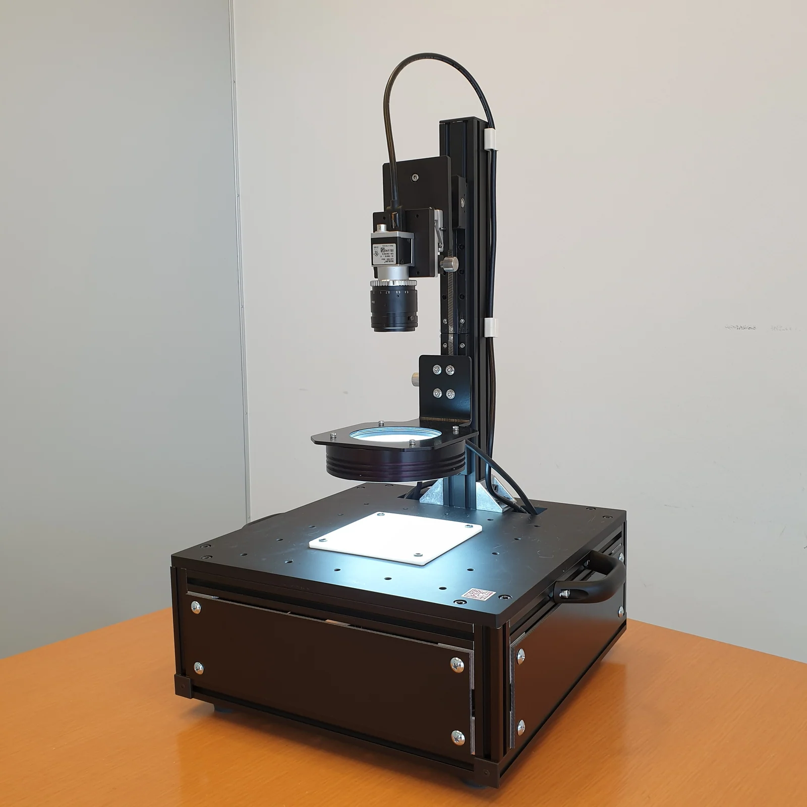
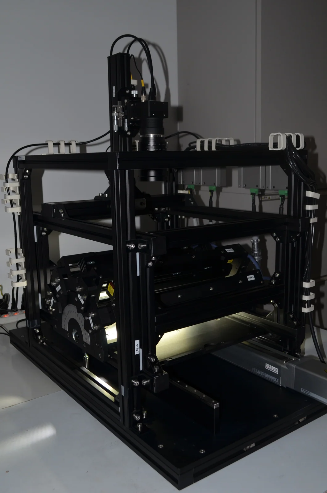
An observation unit built on FORESIGHT STEREO. Set the sample down, press the button, and Live / 2D Texture / 3D Surface / Surface Normal come back at the same time. No dedicated facility, no specialist procedure.
What it shows
What was lost in the reflection
stands up as shape.
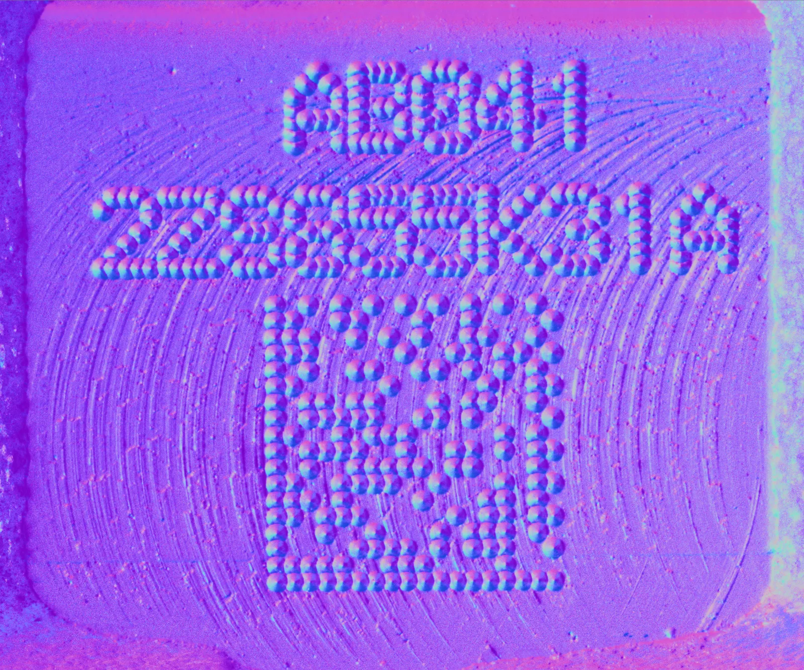
Light from many directions gives the surface normal — the direction the surface itself faces. The normal does not depend on the lighting, so the state of the surface appears the same however the light falls.
◀ Drag to compare ▶
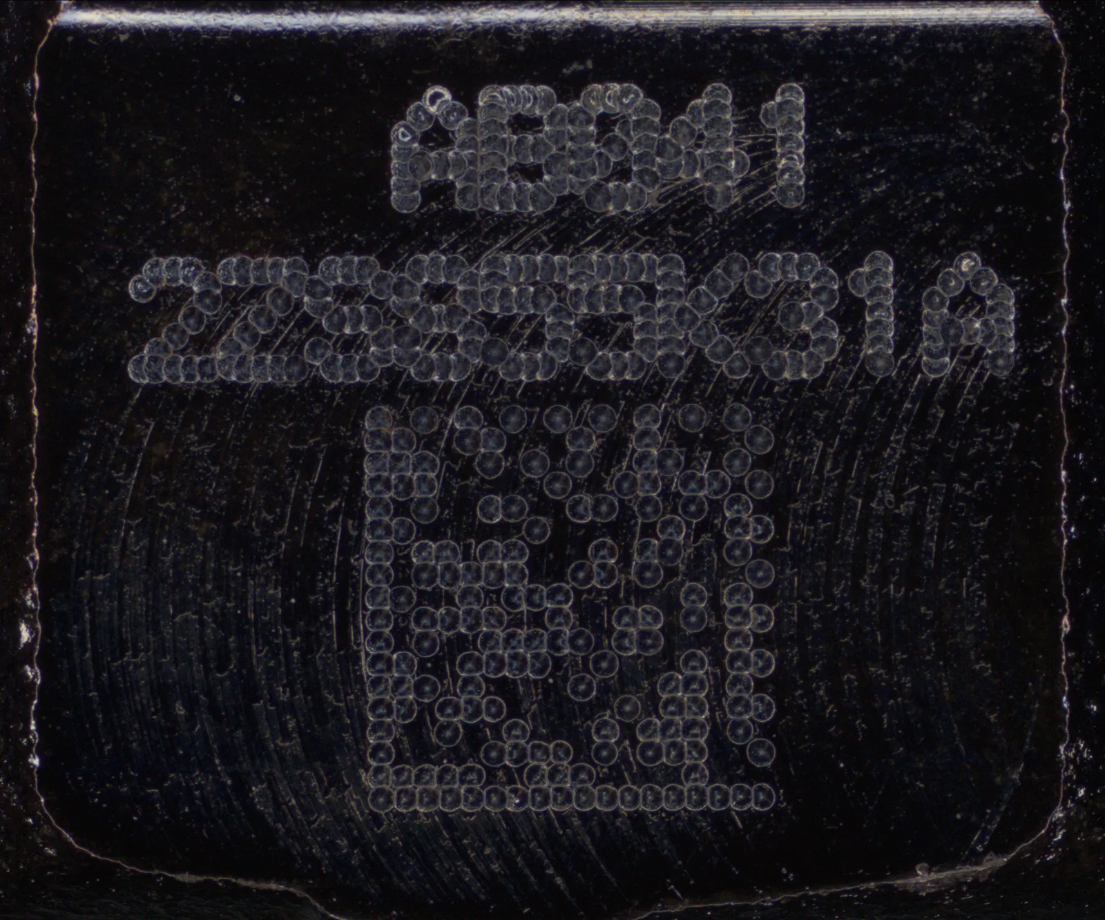
A marking on a black part. The identifier and DataMatrix code, which sink into the black face in an ordinary capture, come up in the surface normal as one hollow after another.
Four outputs
One capture. Four outputs.
The same sample comes back in four ways at once. Depending on what you need to see, you can read it by colour, by shape, or by direction.
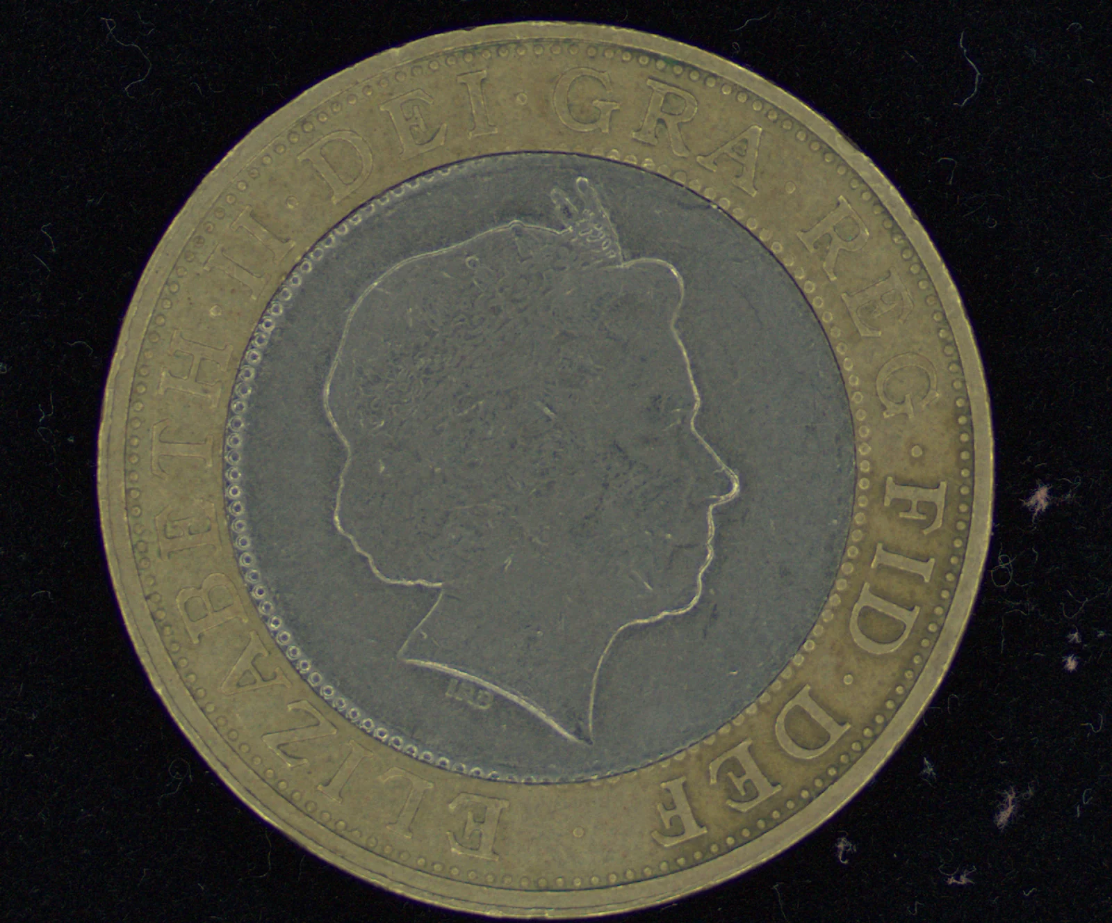
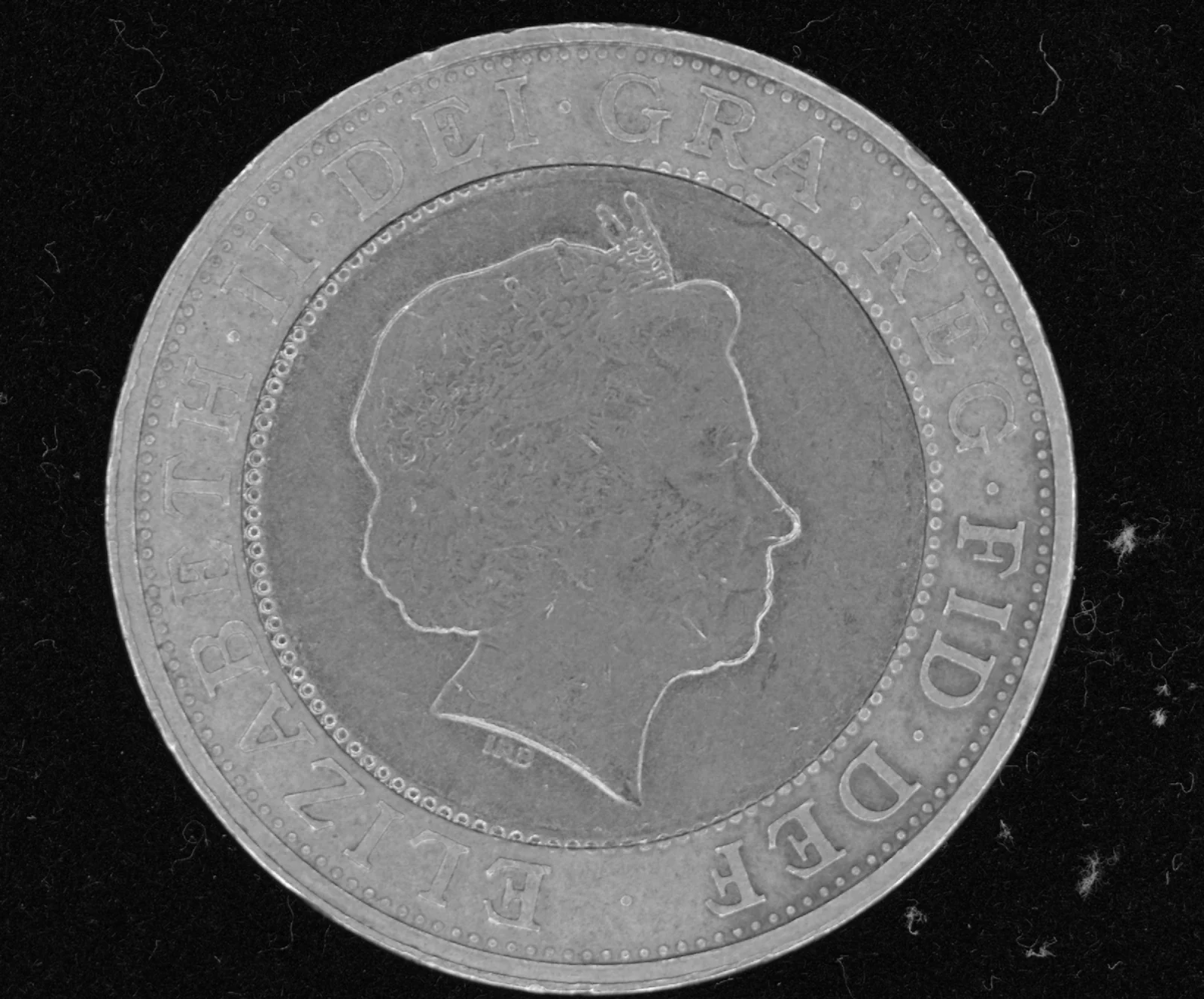
The image as the eye sees it.
The ordinary capture, kept as the reference. Reflections and shadows remain.
Shading discarded, material kept.
The lighting is taken out and the albedo extracted. The outer ring and the inner disc differ in reflectance.
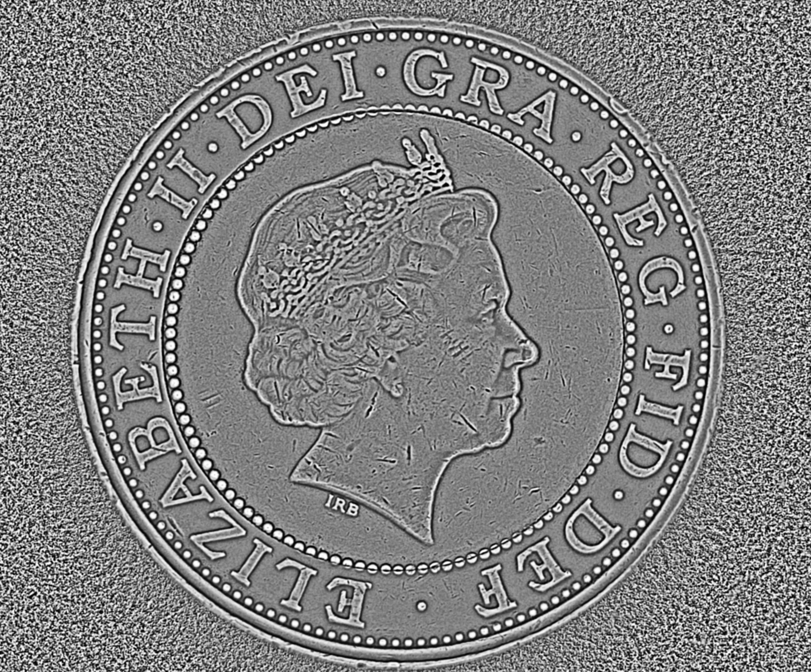
Material discarded, shape kept.
The bimetallic boundary disappears; fine scratches and the tiny mark “IRB” come out as shape.
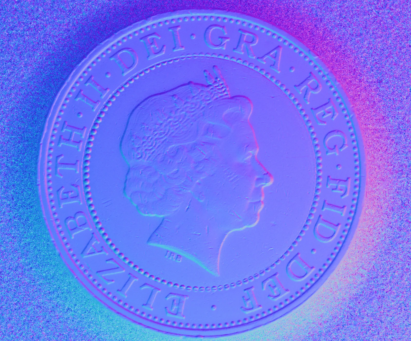
Surface direction, encoded as colour.
A feature independent of the lighting. The physical quantity at the core of FORESIGHT STEREO.
3D reconstruction
And then, observed as solid.
The surface shape is recovered from the estimated normals, and the face can be examined from any viewpoint. Relief that a single view from directly above could not read becomes clear the moment the angle changes.
Display modes — shaded, normal, pseudo-colour and others — can be switched to suit what you are looking for.
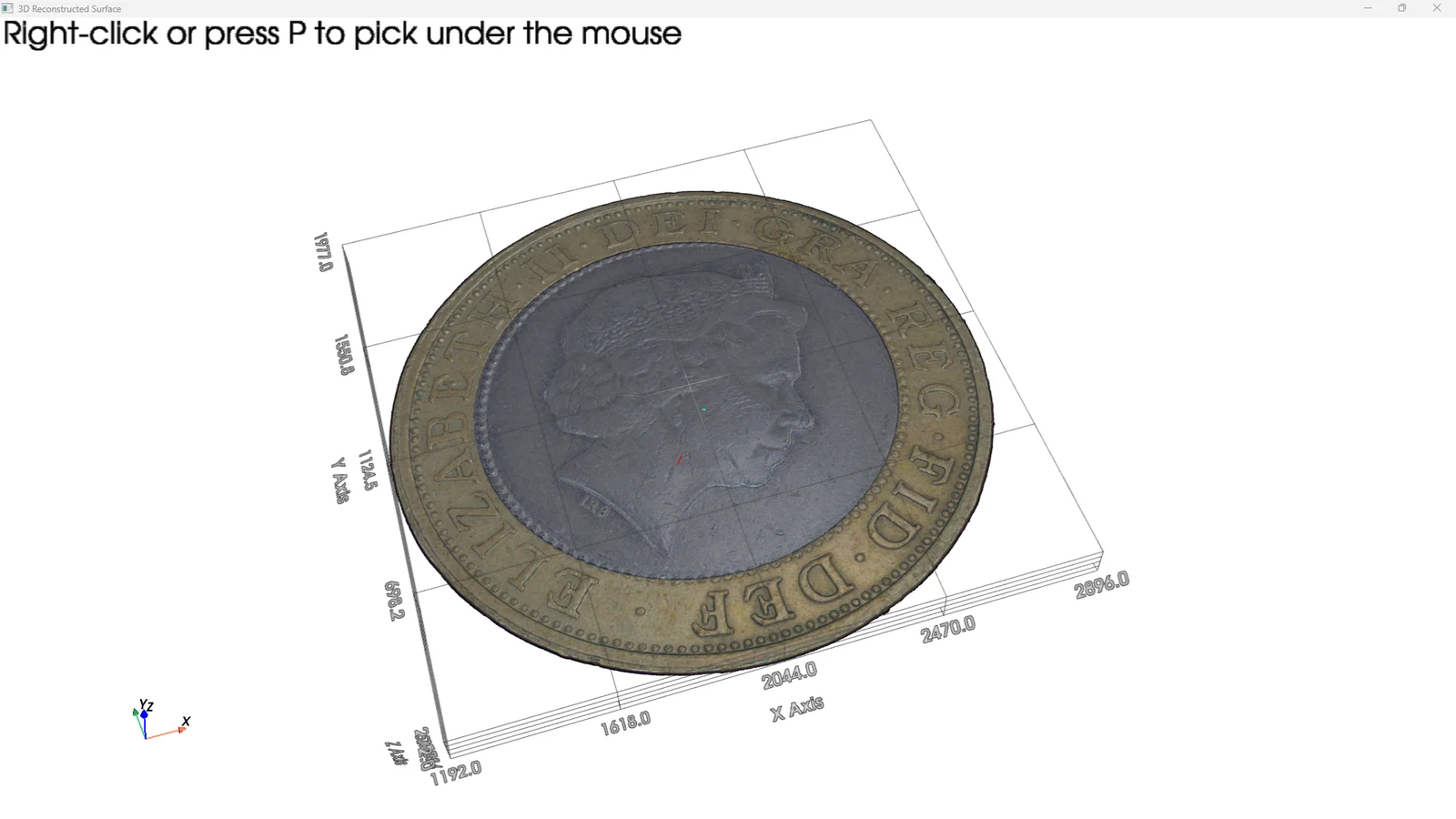
The recovered surface, examined freely in the Viewer.
Use cases
Where it is used.
It suits work where the difference you need is in shape, not in colour or brightness.
Machined surfaces
Observing machined faces of metal and plastic as shape.
Wear and degradation
Seeing how a surface has changed through use.
Relief and marking
Checking that relief or marking on a prototype came out as intended.
Low colour contrast
Objects where colour barely differs and only the shape has changed.
Research and teaching
For research and teaching at universities and research institutes.
Building datasets
Producing datasets for image processing and machine learning.
〔要確認〕 These are the uses published as of the announcement on 2026-07-21. Whether installations and customer names may be named needs separate confirmation.
Specifications
What has been published.
Only what has been published is given here. Items not yet published are marked 〔要確認〕.
| Category | Observation unit |
|---|---|
| Core technology | FORESIGHT STEREO® (a 3D imaging technique developed from photometric stereo) |
| Outputs | Live / 2D Texture / 3D Surface / Surface Normal (all four from a single capture) |
| 3D reconstruction | Supported (3D Surface Reconstruction; examined from any viewpoint) |
| Display modes | Shaded / normal / pseudo-colour, and others |
| Operation | Set the sample down and press the button. No dedicated facility or specialist procedure |
| Bundled software | FORESIGHT STEREO® Viewer (displays the four outputs; 3D observation) |
| 3D image generation time | 30 ms※1 |
| 3D processing condition | 4MP × 4 images |
| Objects | Semiconductors and electronic components (chip surfaces, scribe lines, marking and steps on packages); samples in materials research (machined, worn and fracture surfaces of metal, plastic, ceramic and composite); packaging and mounting (solder, sealing faces, plated faces). The main targets are surfaces where colour barely differs and only the shape has changed. Work size is whatever fits inside a benchtop cabinet. |
| Camera | Standard is an 8.3 MP area-scan camera. Up to 24.4 MP can be specified. |
| Field of view and resolution | Field of view ranges from about 50 mm in diameter at the narrow end to 150 mm square. Camera, lens and working distance are selected according to the object and the size to be detected. Pixel resolution is the field width divided by the horizontal pixel count of the camera. We recommend that the resolution you need be settled by prior evaluation on your own samples. |
| Dimensions | W 320 × D 320 × H 600 mm (benchtop) |
| Power and environment | Indoor use. Power: AC 100 V. The PC is selected to suit the configuration. |
| Announced | 2026-07-21 |
| Supply | Quoted individually according to configuration |
※1 4MP images × 4, on an RTX 3060 6GB. From photometric stereo processing through to generating 3D Surface, 2D Texture, Surface Normal and the rest. AI decision is not included — TR-55 does not decide.
※ TR-55 is a unit for observation, and does not guarantee measurement results. “Visible” here means physically based observation and visualisation, not generative estimation. Specific figures on accuracy have not been published 〔要確認〕.
Where it sits
TR-55 in the three layers.
Our products are built in three layers. TR-55 sits in the systems layer, in a configuration intended for observation.
FORESIGHT STEREO®
A 3D imaging technique developed from photometric stereo. From illumination in many directions it takes the surface normal, independently of the lighting, and recovers 3D shape. TR-55 uses this technique.
E3 ENGINE®
The anomaly detection engine. It learns from good products only and puts a number on the “something not present in a good one” that an inspector senses. It is not part of the TR-55 configuration — TR-55 is for observation.
TR series
The systems that carry the sensor. The configuration is chosen to suit the conditions and the purpose. TR-55 is for observation; TR-300 is the 3D × AI inspection system for continuous inspection on a moving line.
Related
Related products
The core technology TR-55 uses. A 3D imaging technique that takes the surface normal, independently of the lighting, from illumination in many directions.
Read more →
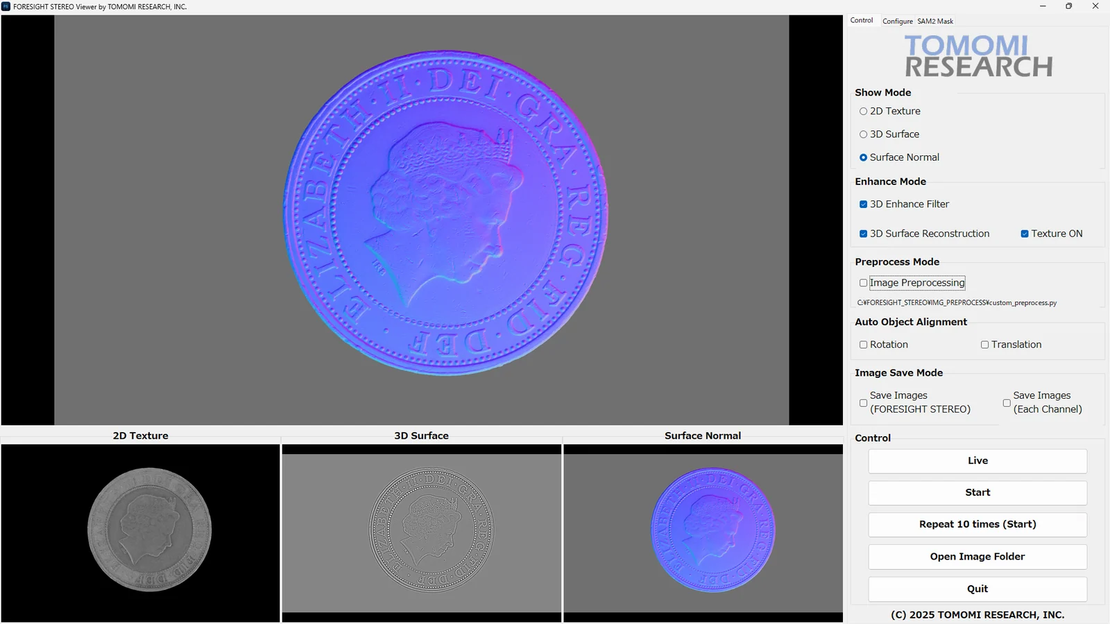
For examining the four outputs and the recovered 3D shape from any viewpoint. Bundled with TR-55.
Continuous inspection that forms a 3D image on a moving line. Winner of the Kanagawa Industrial Technology Development Award, Future Creation Prize.
Read more →
Contact
If what you need to see
is not yet visible.
Tell us the material of the object, the size of the shape you need to see and how it is used, and we will work out together whether TR-55 can show it. A trial capture on your own sample can be arranged.