
Line scan camera
On a line that never stops,
one row at a time.
A line scan camera is a camera whose pixels form a single row. It captures one row at a time as the object moves past, and stacks the rows into one image. Steel sheet, film, long parts — anything that cannot be stopped to be photographed is captured this way.
Photometric Stereo, however, was a method that assumed the object stays still. We bring it onto a moving line by switching the lighting row by row and synchronising it with the conveyor. This page is here so that you can try the mechanism for yourself, rather than just read about it.
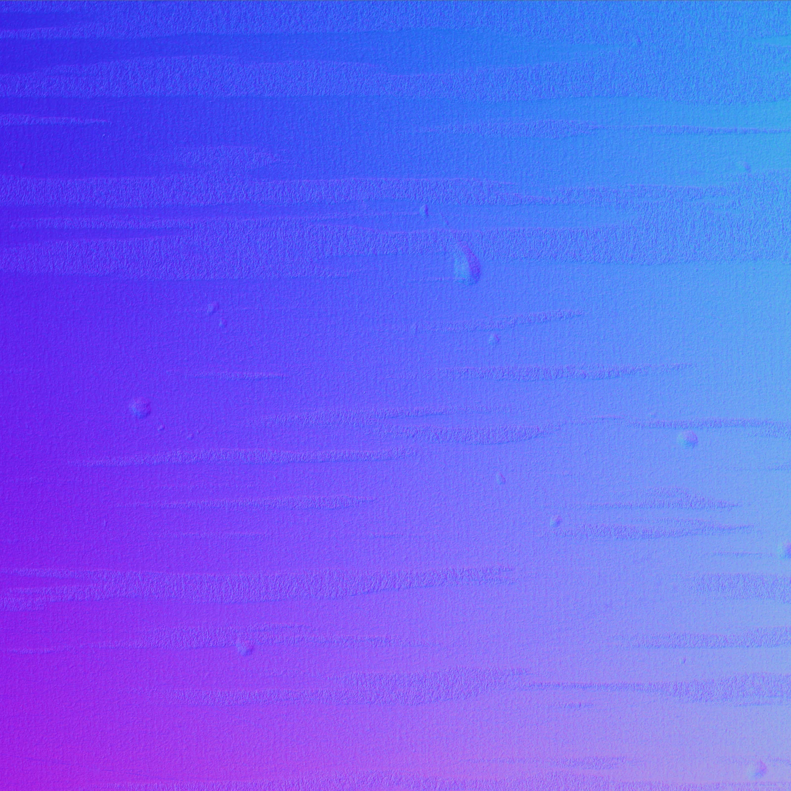
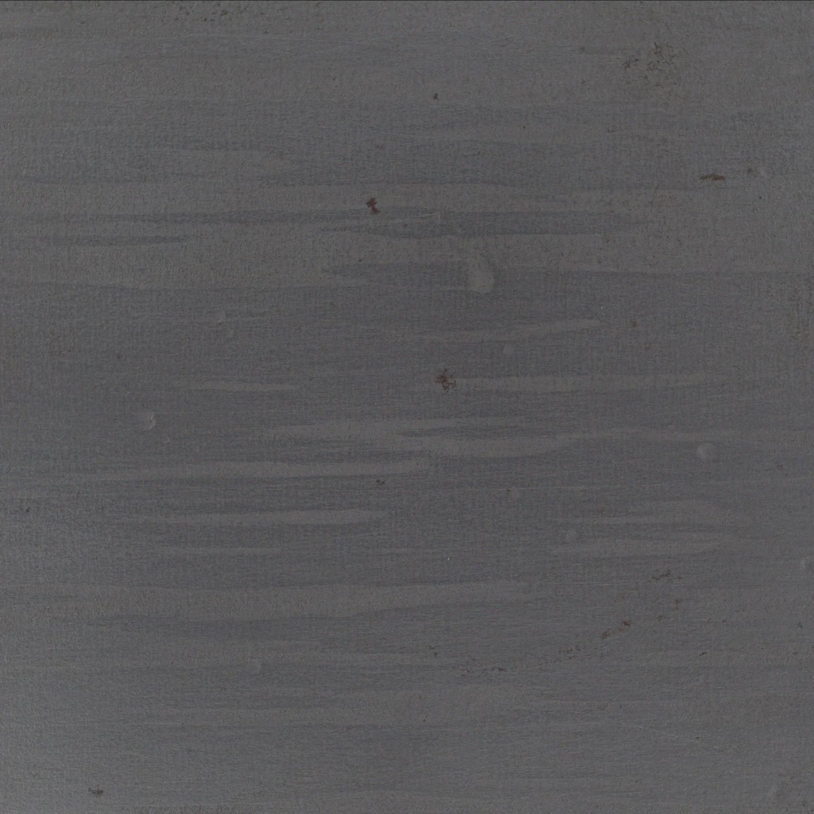
◀ Drag to compare ▶
A press dent in steel sheet, captured with TR-300 in its line-scan configuration. From an image taken one row at a time, the surface direction is solved as well. Experiment 01 on this page uses this steel sheet image.
Experiment 01
The height of the image is set
by the conveyor, not the camera.
The image below is the steel sheet above, reassembled on the assumption that it was "captured one row at a time". Move the conveying speed and the line rate (the number of rows captured per second). The horizontal pixel size is set by the camera, but the vertical pixel size is set by how far the object travels while one row is captured.
Assembled image (512 columns wide × 512 rows tall. The horizontal pixel size is taken as about 73 μm, for a 4K camera across a 300 mm width)
60 m/min
13.7 kHz
Distance travelled per row (vertical pixel size) —
Vertical pixel ÷ horizontal pixel —
Line rate that equalises the two at this speed —
The input is the Live image of the steel sheet above (512 px, greyscale). The distance travelled per row is found as feed = conveying speed ÷ line rate, and rows of the original image are read out at that interval and stacked (with linear interpolation between rows). With encoder sync, the feed is fixed at the horizontal pixel size. Acceleration is simulated as a speed that rises linearly to 1.6× from the start to the end of the capture.
The biggest difference from an area camera.
With an area camera, the vertical and horizontal pixels are fixed in one go. With line scan, only the horizontal is set by the camera; the vertical is created by the conveyor. Too fast and the image is squashed vertically; too slow and it is stretched — with this method, the shape of the image changes with the behaviour of the line. That is why, on the shop floor, an encoder that passes the conveyor's own motion to the camera is indispensable.
With an encoder, speed stops mattering.
An encoder is a component that reports "how far it has moved" as pulses. Capture one row on each of its signals, and even if the speed wavers or accelerates, the feed per row is always the same distance. In our line-scan configuration too, the encoder is where the signals to the lighting controller and the camera originate (→ see the diagram in How it is synchronised).
How it is synchronized
Switch the lighting as it flows,
then re-align afterwards.
Photometric Stereo captures the same place several times, with light from different directions (→ What is Photometric Stereo?). If the object is moving, the place in the first image and the place in the second no longer match — this is why the method is said to assume that the object stays still.
Our configuration switches the lighting direction for each row, learns the position of each row from the encoder signal, and collects only the rows captured under the same lighting direction, re-aligning them by position. Once the images for all four directions are complete, the surface direction is solved with the same equation as for a stationary object.
Sources: the system diagram in our handout "FORESIGHT STEREO for line scan cameras" (2025-08), and the statement in our company profile (2026-02): "LED lighting in 4 directions switched at high speed for every line, synchronised with the conveying speed". The line-scan configuration (TR-300) has lighting in 4 directions; the area-camera configuration (TR-100) has 8. We do not publish the details of the switching order or timing.
The signals start at the encoder. Because the lighting and the camera act on the same signal, the position of each row is known and the rows can be re-aligned afterwards.
Experiment 02
Re-align, and it solves.
Drift, and it breaks down.
From the measured normals and albedo of a coin, we create the four images you would get by "running it past while switching four lighting directions row by row", and solve the surface direction again from them. Check what happens when you add sync offset, and what happens when you turn off re-alignment, by the error against the measured normals.
Re-solved normals (surface direction encoded as colour)
Images captured under four lighting directions, switched row by row (simulated)
Each image has only one row in four filled. They are re-aligned by position and the gaps are filled in before use.
Re-alignment
0.0 rows
When the lighting switch lags behind the camera signal, the place captured drifts further with each direction.
Deviation from the measured normals (mean angle) —
The four images are simulated (we apply I = ρ (n · l) to the measured n and ρ, add uniform random noise of ±2%, and assign the lighting by the remainder of the row number divided by 4). The lights are placed at azimuths of 45°, 135°, 225° and 315°, at an elevation of 38°. This is not the lighting arrangement or switching order of our actual system; it is an arrangement for showing the mechanism. The normals are solved by the same least squares as in Experiment 02 on Photometric Stereo →.
Why "stacking as they are" breaks down.
Each of the four directional images holds one row in four, and each of those rows shows a different place. Stack them while ignoring position, and the brightness of other places gets mixed into the surface-direction equation, so the normals are disturbed at edges and stamped relief. Only after re-aligning by the encoder's position information and filling the missing rows from their neighbours do the four images become "four images of the same place".
Synchronisation is measured in microseconds.
On a 100 m/min line with 73 μm per row, one row takes about 44 μs. If the lighting switch lags by more than this, the place captured drifts by whole rows from one direction to the next. That is what the "offset" on the slider represents. This is why our configuration drives the lighting controller and the camera from the same signal.
On a real line
Sheets and long parts,
made 3D without stopping.
FORESIGHT STEREO in the line-scan configuration produces the same outputs as with an area camera: 2D Texture / 3D Surface / Surface Normal. Here are the examples in our handout, alongside the figures we have published.
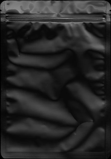
Shape sinks into uneven gloss.
A pouch-type EV battery. On the black glossy face, damage hardly shows up as a difference in brightness.
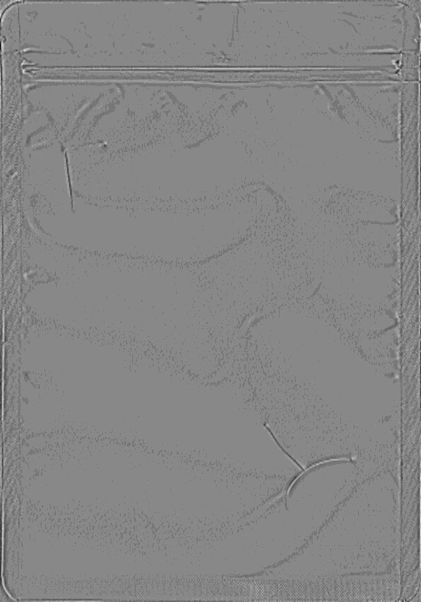
Still moving, it stands out as relief.
Captured in the line-scan configuration. The uneven gloss drops away, and the linear damage remains as shape.
* Both images appear in our handout "FORESIGHT STEREO for line scan cameras" (2025-08). The handout does not give the detailed capture conditions, so only the images are shown here.
The figures we publish.
Where sources give different figures for the same item, we list both with their sources and mark which one is authoritative as 〔要確認〕.
| Camera | 2K / 4K / 8K / 16K line scan camera (GigE) Source: handout 2025-08; TR-300 specifications 2026-08 |
|---|---|
| Lighting | Line lights supporting high-speed strobing, in 4 directions (TR-300, line-scan configuration) Source: handout 2025-08 (made by Leimac); company profile 2026-02; confirmed by us 2026-08-22 TR-100, in the area-camera configuration, has 8 directions. |
| Synchronisation | Encoder → lighting controller → camera → PC/GPU Source: system diagram in handout 2025-08 |
| Processing time | 30 ms (up to generation of the 3D image; 4 MP × 4 images; RTX 3060 6GB) Source: handout 2025-08; confirmed by us 2026-08-22 60–80 ms (typical processing time including AI judgement) Source: TR-300 specifications 2026-08 |
| Conveying speed | 40–100 m/min Source: handout 2025-08 / up to 200 m/min Source: TR-300 announcement 2026-04〔要確認:条件の違い〕 |
| Field of view and pixels | Imaging width is set to suit the application. With an 8K camera across a width of 100 mm, one pixel is about 12.2 μm (theoretical value) Source: TR-300 specifications 2026-08 |
| Minimum detectable anomaly size | Depends on capture conditions and defect shape Source: TR-300 specifications 2026-08. Not published as a single figure Why it is not a single number → |
| Outputs | 2D Texture / 3D Surface / Surface Normal |
| Configuration | GPU + PC (no FPGA or dedicated boards) Source: handout 2025-08 |
* All figures are our published values, measured under the conditions given in their sources. They vary with the object and the capture conditions, so they do not indicate performance on your actual object. For TR-300's product specifications, the TR-300 page → is authoritative.
Experiment 03
How much data flows?
The data rate of a line scan camera is set by width × bytes per pixel × line rate (the formula from our technical blog, 2024-11-15). Note that in a configuration that switches four lighting directions row by row, the line rate must be four times higher to keep the same feed.
Data rate
Per second—
Switching 4 directions row by row—
Example: 4,096 pixels × 1 byte × 3,300 Hz = 13.5 MB/s = about 108 Mbps (the example in the technical blog). Even on 1 Gbps GigE, raising the width and speed quickly brings you close to the limit.
On the bench
From a single line scan camera,
all the way to 3D.
Footage captured with TR-300. Switch the lighting while the object flows past one row at a time, re-align afterwards, and the surface direction and relief come out without stopping. What you saw break down "with drift" in Experiment 02 is here, held in line on a real system.
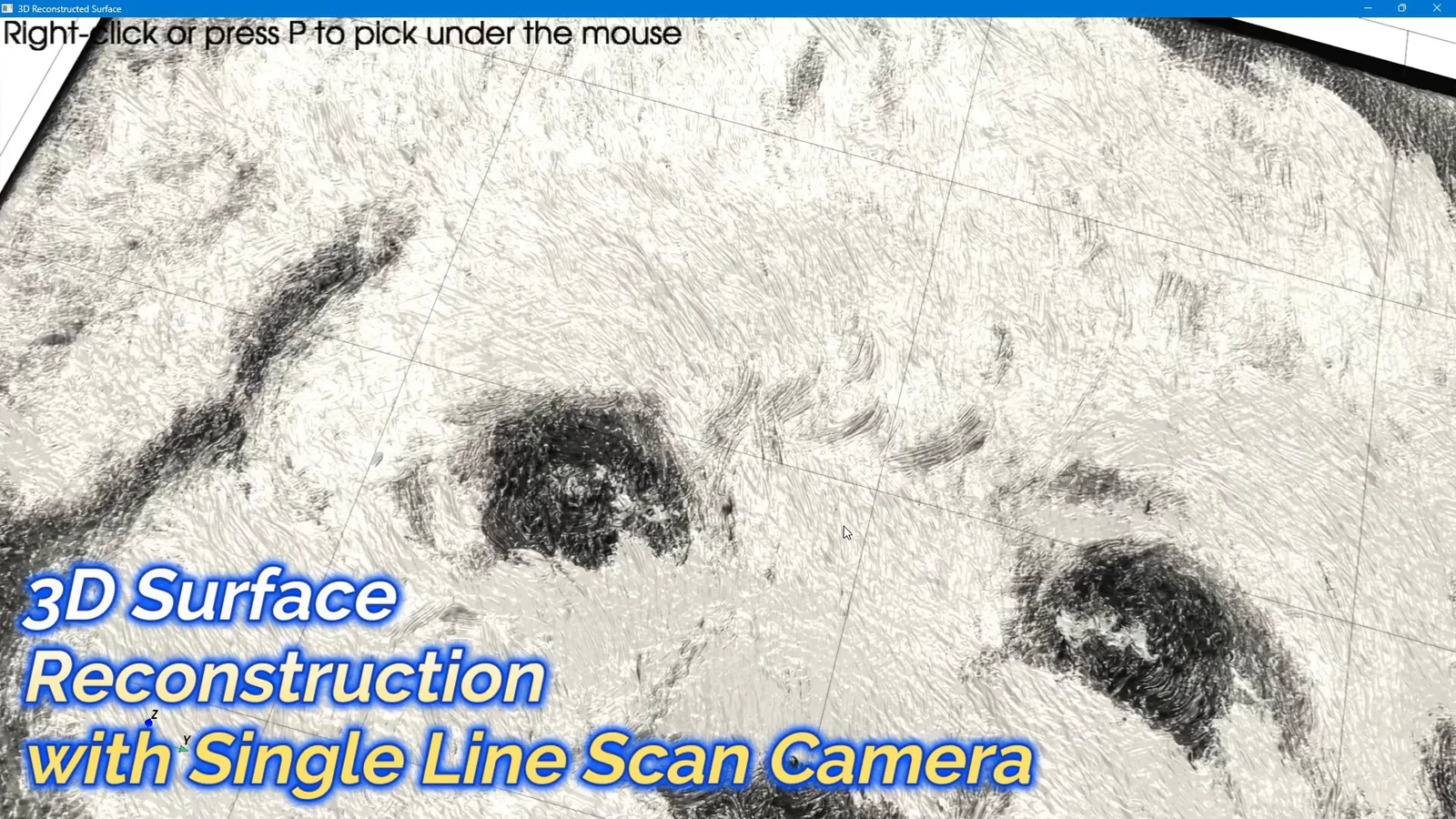 0:53
TOMOMI RESEARCH / YouTube Watch on YouTube ↗
The footage is real output from our own system. The video is in Japanese. Nothing is loaded from YouTube until you press play (at that point the player switches to youtube-nocookie.com).
Strengths and limits
The other side of
capturing one row at a time.
Line scan and area cameras are exact mirror images of each other in what they are good and bad at.
| Line scan camera | Area camera | |
|---|---|---|
| Suited to | Things that are moving, long or wide (steel sheet, film, sheet materials) | Things that can be stopped, or placed one at a time |
| Image height | Created by the conveyor. The feed is set by the encoder | Created by the camera. Place the object and capture it as it is |
| What it needs | Conveyor, encoder, line lighting, synchronisation | Camera and lighting |
| Photometric Stereo | Switch the lighting row by row, re-align, then solve (our configuration) | Stop, capture N images, solve as they are |
| Exposure | The short time of a single row. Needs light output and strobing | One full frame. Can be relatively long |
* This is a general comparison between methods and does not indicate the performance of any individual product.
There are clear weaknesses, too.
This method rests on two things: that the object flows at a steady pace, and that the position of each row is known.
With only one row, there is no image unless the object or the camera moves. For applications where the object is placed and captured, an area-camera configuration (TR-100, TR-55) is the better fit.
As in Experiment 01, if the speed wavers, the image stretches and squashes. Synchronising to distance with an encoder is the premise, and on a conveyor with slip or vibration that premise breaks down.
As in Experiment 02, if the lighting switch drifts from the camera signal, each direction images a different place. Our configuration ties these to the same signal, but checking the wiring and settings is part of the work at installation.
The exposure for one row is short, and switching directions makes the time per direction shorter still. Strong strobing is needed. And as in Experiment 03, raising the width and speed makes the data grow sharply.
We hold to this method because the things that cannot be stopped are exactly the ones we want to inspect in full. Coils of steel sheet, rolls of film, long parts — rather than pulling samples and stopping them to capture, we solve them down to surface direction as they flow. The system that does this is TR-300.
Where it sits
Where does this configuration sit?
Line scan support is one of the configurations of the sensor (FORESIGHT STEREO). Built into a system, it becomes TR-300 in Layer 03.
FORESIGHT STEREO®
A 3D imaging technology that obtains the surface normal, illumination-invariant, from multi-directional lighting. It comes in an area-camera configuration and a line-scan configuration. How the normals are solved →
E3 ENGINE®
An AI anomaly detection engine that learns from good products only and quantifies how far a product departs from them. It judges the images built from the incoming rows as they are. How the judgement works →
TR-300
A continuous inspection system that brings the sensor in its line-scan configuration and the judgement engine together in one unit that runs on a moving line. See the product →
* The standalone software AI SMART MASK sits outside these three layers (it is preprocessing that decides "where to look", and does not make OK/NG judgements).
Related
How do you look at things that move?
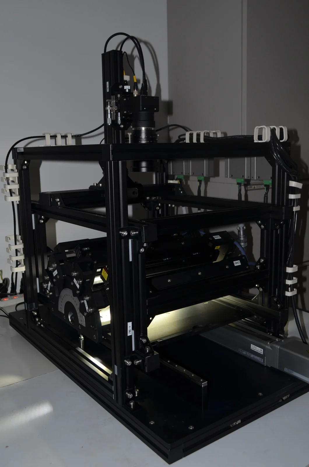
The configuration on this page, as a product. It captures the work as it flows, turns it into 3D and returns a judgement.
Read more →
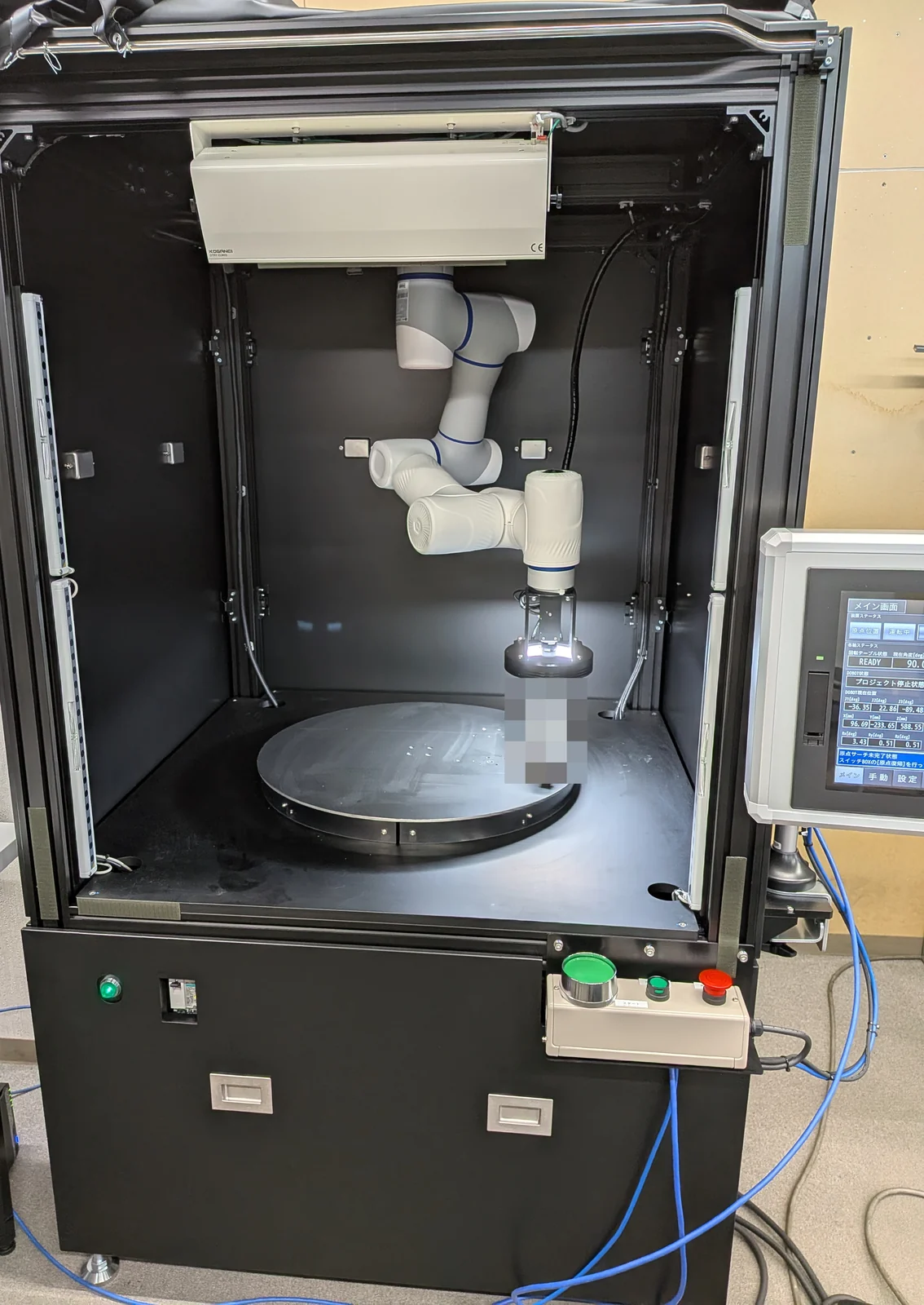
The other answer: move the sensor rather than the work. It goes around complex shapes to capture them.
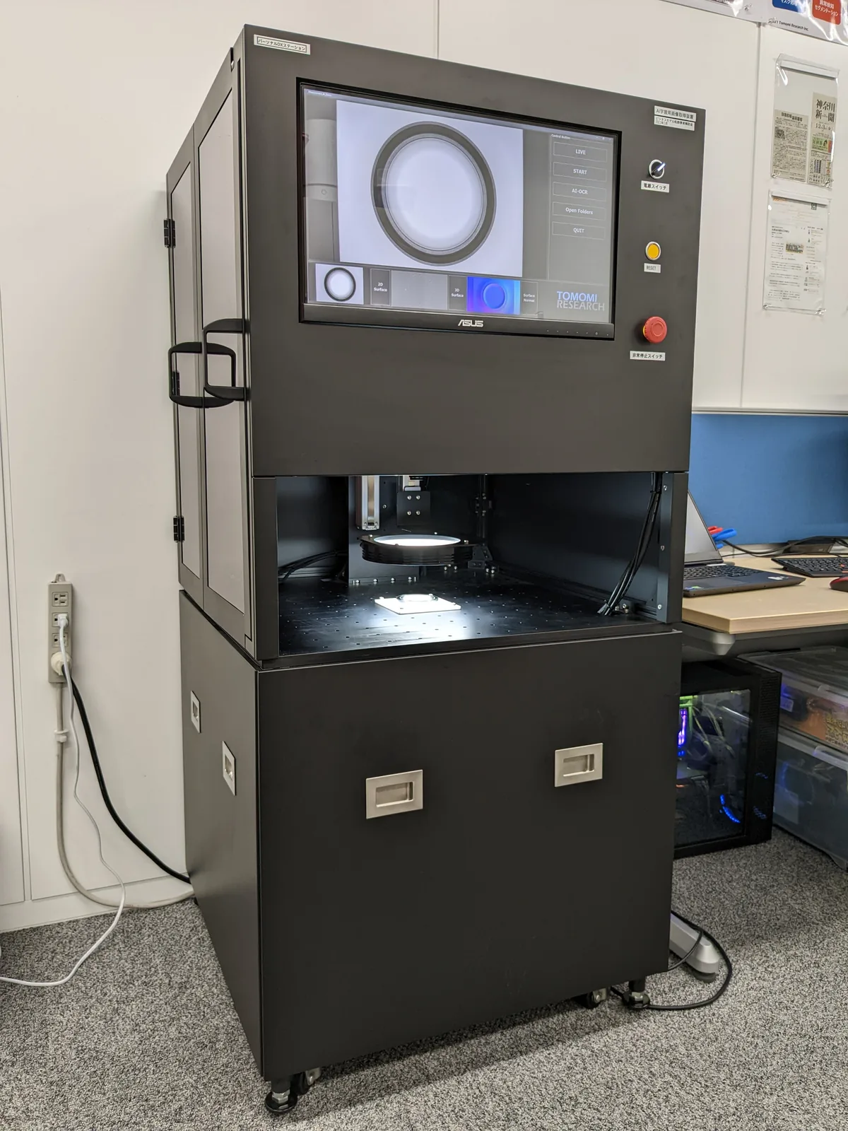
The area-camera configuration, which stops to capture. If the object can be placed, this is the straightforward choice.
Read more →
Contact
Can your line be captured
without stopping?
Whether it can depends on the conveying speed and width, the surface finish of the object, and whether an encoder signal is available. This is as far as a screen can take you. Tell us about your line's conditions, and let us start by running samples through and capturing them.