
Materials
The same system.
A different object, a different view.
“Can you see our parts?” — it is the question that comes up in every meeting. The answer is decided not by the system but by how the surface of the object returns light.
Jet-black plastic, shiny plating, a clear coating, fine relief. Using six materials we captured ourselves, we set the photograph (Live) beside the surface direction (Surface Normal) to show how they differ. Every one is a real measurement.
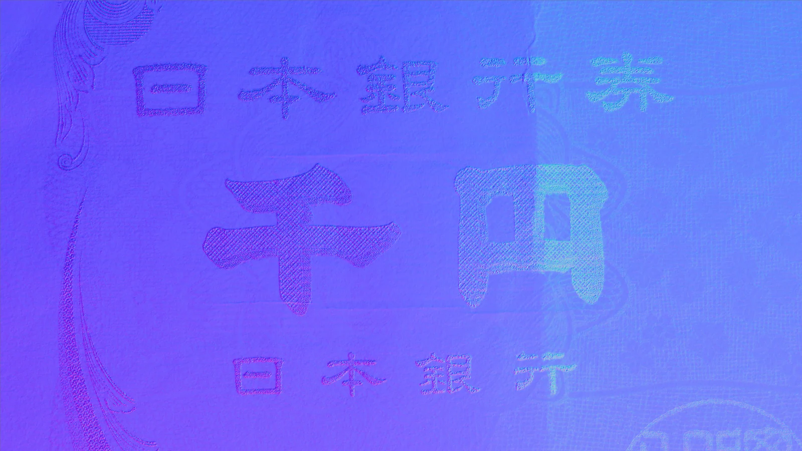

◀ Drag to compare ▶
A 1,000-yen note. In the photograph, colour and pattern dominate; in the surface direction the colour disappears and only the relief of the intaglio printing remains. This is what we mean when we say the two measure different things.
Experiment 01
The photo line is flat.
The direction line has structure.
Choose an object and the page cuts one row at the same place and plots its brightness next to its surface tilt. You can move the scan line up and down.
The more uniform an object looks in a photograph — steel sheet, rubber — the more the two lines below differ in character. The photo line stays flat; only the direction line has structure.
Row 192
Live (photograph) σ 4.6
Surface Normal (surface direction) σ 0.196
You can also drag on either image to move the scan line.
σ (sigma) is the size of the spread.
It is how widely the values are scattered within that one row. The smaller the brightness σ, the flatter and more featureless the photograph. The larger the direction σ, the more places where the surface is tilted.
Choose the steel sheet and the two point in opposite directions. It looks flat in the photograph, yet in the surface direction the rolling lines and the dent show clearly.
The images are not processed.
For all six, we took the measured Live and Surface Normal that we captured ourselves, cut a square from the centre and reduced it to 384 pixels. Nothing else. Neither contrast nor colour has been touched.
* The two lines in the graph are computed on the spot from those images. Brightness is the greyscale of Live (0–255); tilt is the magnitude of the horizontal component of the normal, √(nx² + ny²) (0–1).
The assumption
There is only
one assumption.
All that Photometric Stereo assumes is that the surface scatters light with the same brightness whichever direction it is viewed from (diffuse reflection). As long as that holds, changes in brightness are decided by the surface direction alone.
In the end, the “difference in how each material appears” is a difference in how it departs from this assumption. There are only four ways to depart.
Cases 1–3 break the assumption itself, so they call for care in how the object is captured. Case 4 does not break the assumption; it is a question of the amount of light, so it can often be solved with exposure and lighting. Try the equation itself →
Cases 1–3 break the assumption; case 4 departs from it without breaking it. In meetings we are often told “it’s black, so surely it won’t work” — but blackness is case 4.
Experiment 02
Which objects look flat
in a photograph?
For each of the six images we measured the spread of brightness (horizontal) and the spread of surface direction (vertical) across the whole image, and plotted them. The further towards the top left, the less the object differs in the photograph but the more it differs in direction.
Click a point to switch the object in Experiment 01.
* These are values measured from these six images, not constants of the materials themselves. If the lighting, exposure or cropped area changes, the values move too. Read them as a guide to the order.
Top left: the objects that trouble a photograph.
The steel sheet and the rubber sheet land here. Their brightness barely moves in a photograph, so they tend to end up captured but not actually shown. Take the surface direction, and the difference appears.
We started from defect inspection of steel sheet precisely because it is an object in this position.
On the right, look at what the spread is made of.
Plated faces and banknotes show a large spread of brightness, but what it consists of is reflections and printed colour — not the defects you want to see. “The photograph has contrast” and “the defect is visible” are two different things.
Choose the plated face and look at Experiment 01: the brightness line moves a great deal, but you can see that the movement is decided by where the band of reflection falls.
Case by case
Six materials, and how to read each.
Listed in the order we are asked about them. Each corresponds to one of the six images above.
| Object | In the photograph | In the surface direction |
|---|---|---|
| Black plastic Example: laser marking |
It sticks to the dark end. In this image the median brightness is 19/255. The marking is there, but there is no contrast to work with. | The edges of the marking stand up as shape. Blackness does not break the assumption. Only less light comes back, so it is within reach of exposure time and lighting. |
| Plated and glossy faces Plated plastic part for automotive use |
The lighting is reflected as a band, and only that band saturates. Dirt and scratches are lost inside the band. | The gentle change of direction across the curved face comes out. However, pixels in specular reflection fall outside the assumption, so they need treatment — for example, adding lights and discarding them as outliers. |
| Fine relief Regular dimples on a rubber sheet |
It is visible as a pattern, but the spread of brightness is small (the second smallest of the six). | The direction of each individual dimple separates out. The more regular the pattern, the more any disruption stands out. |
| Printed or patterned items Intaglio printing on a banknote |
Colour and pattern dominate, and the thickness of the print is lost in the colour. | The colour disappears and only the raised relief remains. It helps when looking for shape hidden in a pattern. |
| Metal that looks uniform Steel sheet (the object at an actual installation) |
Almost plain. In this image the spread of brightness is the smallest of the six. | The rolling lines and the dent appear. This is the object where the difference is largest. |
| Items with a clear coating Insulating coating of enamelled wire |
The colour of the stranded copper beneath dominates, and damage to the coating hardly shows as colour. | The directions of the coating surface and of the strands beneath both mix in. Where the coating has been crushed, the lines of the strands are disrupted, and it shows as that disruption. |
We do not yet have a real example of a true matte texture (countless random micro-irregularities). It may appear differently from regular relief (the rubber sheet above), so for matte-textured surfaces we will answer with a trial capture 〔要確認〕.
On the bench
Even the build-up of paint
shows in the surface direction.
Experiments 01 and 02 were calculations solved in your browser. Point the real system at an oil painting, and the brushwork and the thickness of the paint come out not as colour but as surface direction. What looked flat in a photograph is seen, as it is, to have structure.
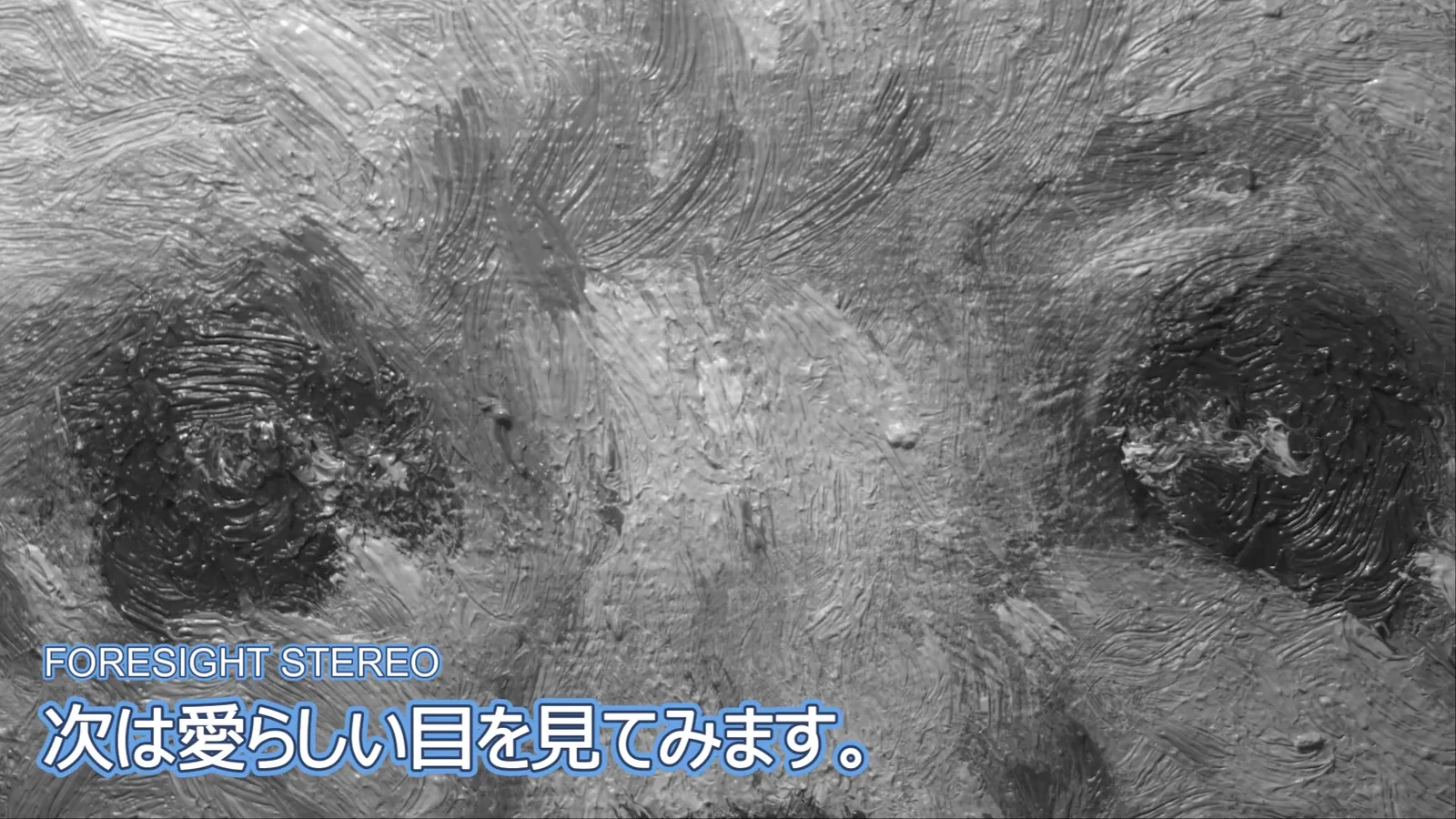 2:01
TOMOMI RESEARCH / YouTube Watch on YouTube ↗
The footage is real output from our own system. The video is in Japanese. Nothing is loaded from YouTube until you press play (at that point the player switches to youtube-nocookie.com).
Limits
What this method finds difficult.
All six objects above can be captured. What cannot be captured is just as clear. Before a trial capture, please check whether your object falls into one of these.
A polished mirror face returns light in almost one direction only. What enters the camera is “an image of the light reflected in it”, not information about surface direction, so the assumption does not hold. Taken in 2D, it comes out either pitch black or full of reflections.
Even so, there is a case where it could be read. When we captured the mirror in our office with TR-300, the height map came out as a uniform grey (that is, flat at the macro scale), and when that was enhanced, fine waviness and line scratches invisible to the naked eye appeared. Even for an object that departs from the assumption, it can sometimes be read by lighting it from many directions and solving it as the shape of the surface.
Translucent plastics, skin, milky-white materials. Light goes inside and leaves from another place, so brightness no longer represents “the surface direction at that pixel”. The image comes out blurred.
Measuring the surface of a transparent body is difficult. The enamelled wire above can be seen because there is copper wire beneath the coating that returns light; we are not measuring the clear layer itself.
The method assumes that several images overlap pixel for pixel. Soft things that change shape and things that vibrate do not overlap. A moving line is handled with a line scan configuration.
For objects not listed here, we do not make definite claims. A slight difference in surface finish can change the result. We have answers only for objects we have actually captured. The quickest answer is for us to take your samples and return the four outputs.
Where it sits
The object decides
the very first layer.
How the surface of an object returns light is a matter for the sensor layer. Once shape is obtained here, the later stages work in the same way.
This is the layer that takes the properties of the surface. Some differences can be absorbed by how it is captured (number of lights, exposure, angle), and some cannot.
You can choose which output to judge on. Even for the same object, the result changes depending on whether you judge on Live or on Surface Normal.
The model is decided by the object’s dimensions, whether it is conveyed, and the takt time. For first capturing samples at hand to check them, there is TR-55.
Related
Capture it first, and check
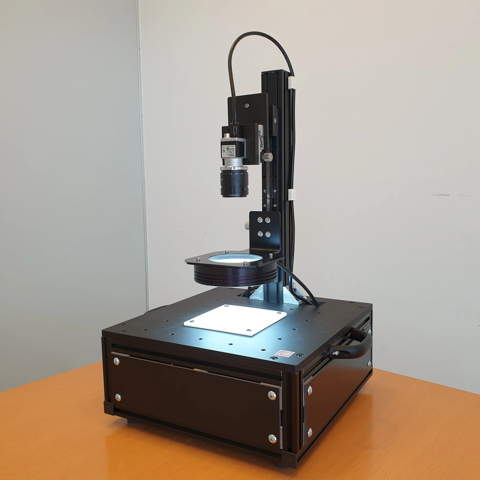
A unit for capturing your own samples and checking them in the four outputs.
Read more →
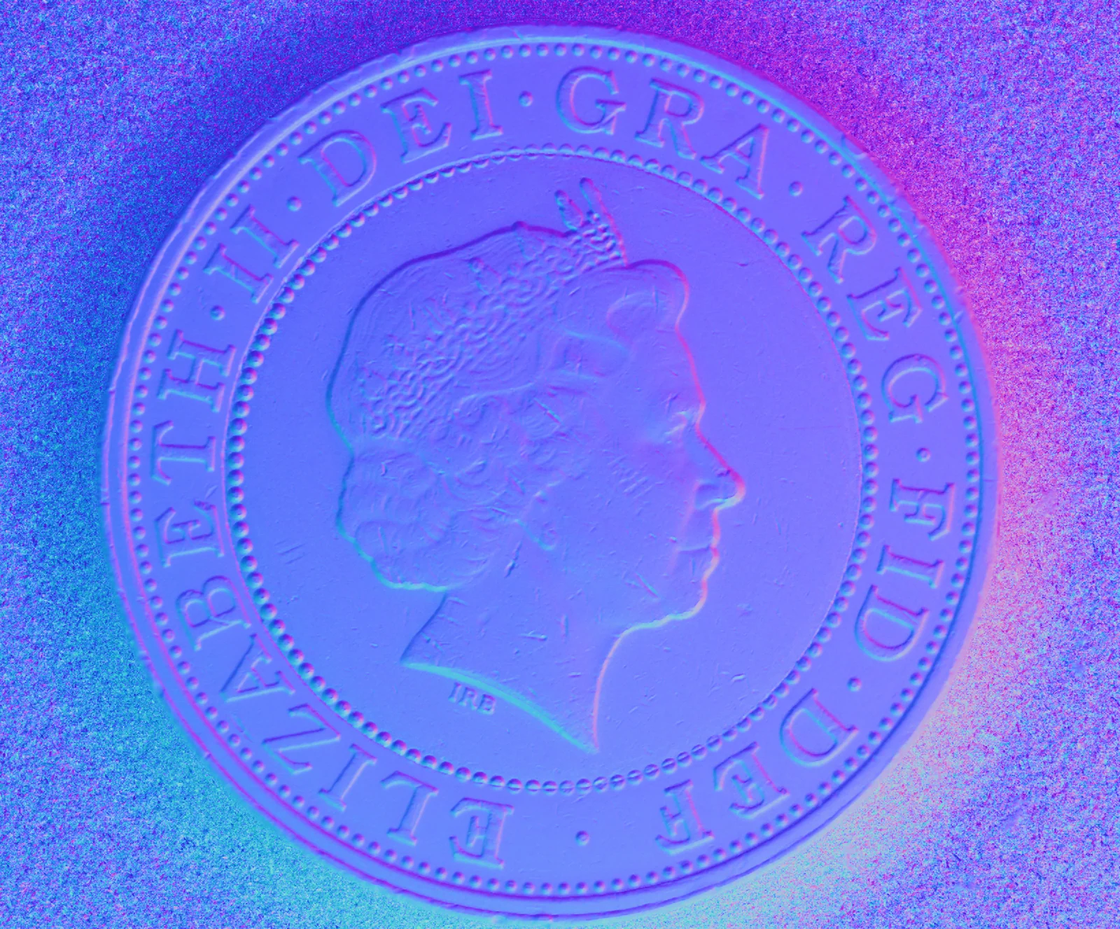
Try the very equation this page rests on, by moving the light yourself.
Read the explainer →
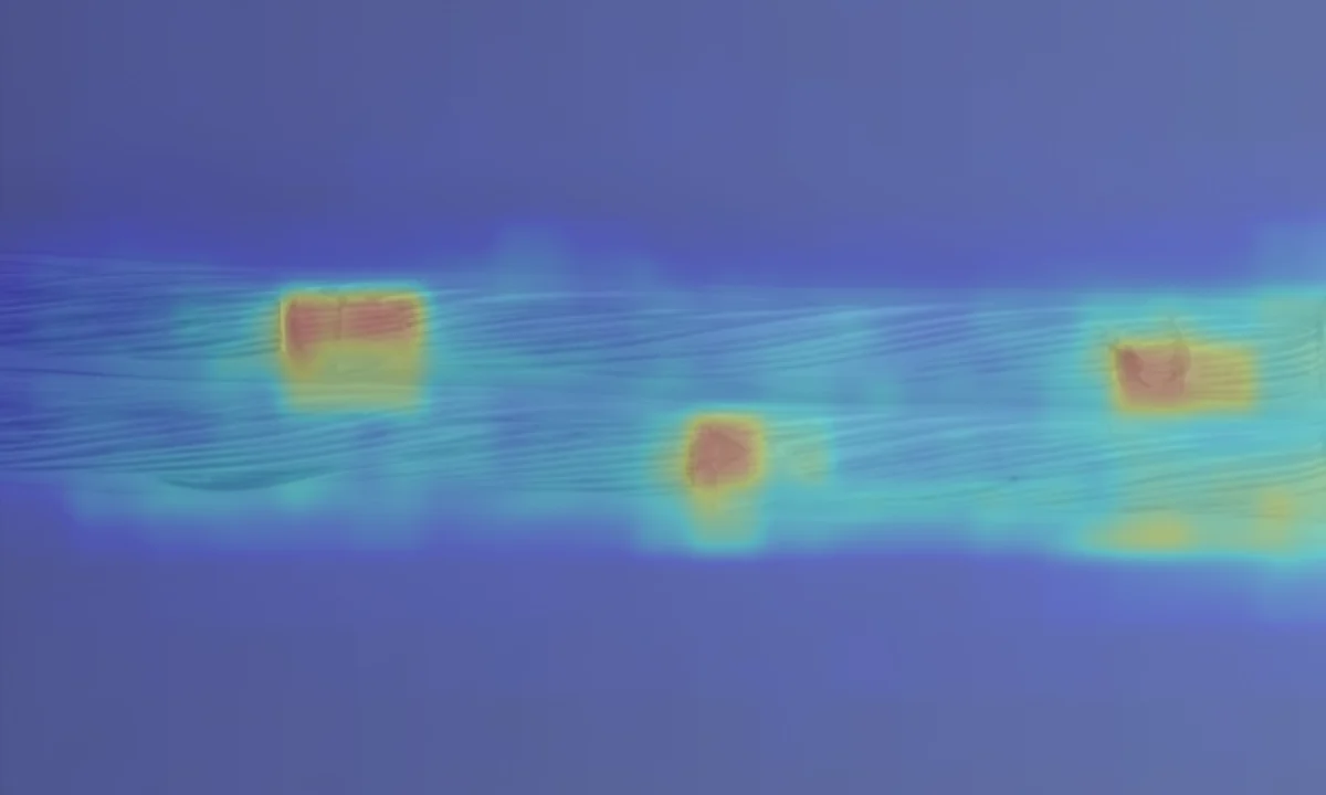
We have measurements of the same enamelled wire judged on Live and judged on Surface Normal.
Read more →
Contact
Which side
does your object fall on?
A slight difference in surface finish changes how an object appears. This is as far as a screen can take us. Start by letting us take your samples, capture them for real and return the four outputs to you.