
Photometric stereo
Move the light,
measure the surface direction.
Photometric stereo keeps both the camera and the sample still and changes only the direction of the light, taking several images. From how the brightness changes, it solves for the direction the surface faces at every pixel: the surface normal.
Its principle is different at the root from stereo or structured light, which measure shape by triangulation. This page is here so that you can check that difference by hand, rather than read about it.
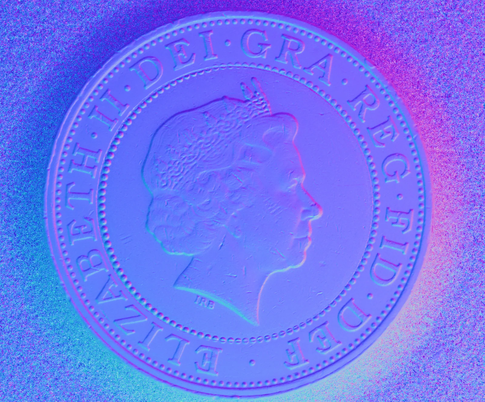
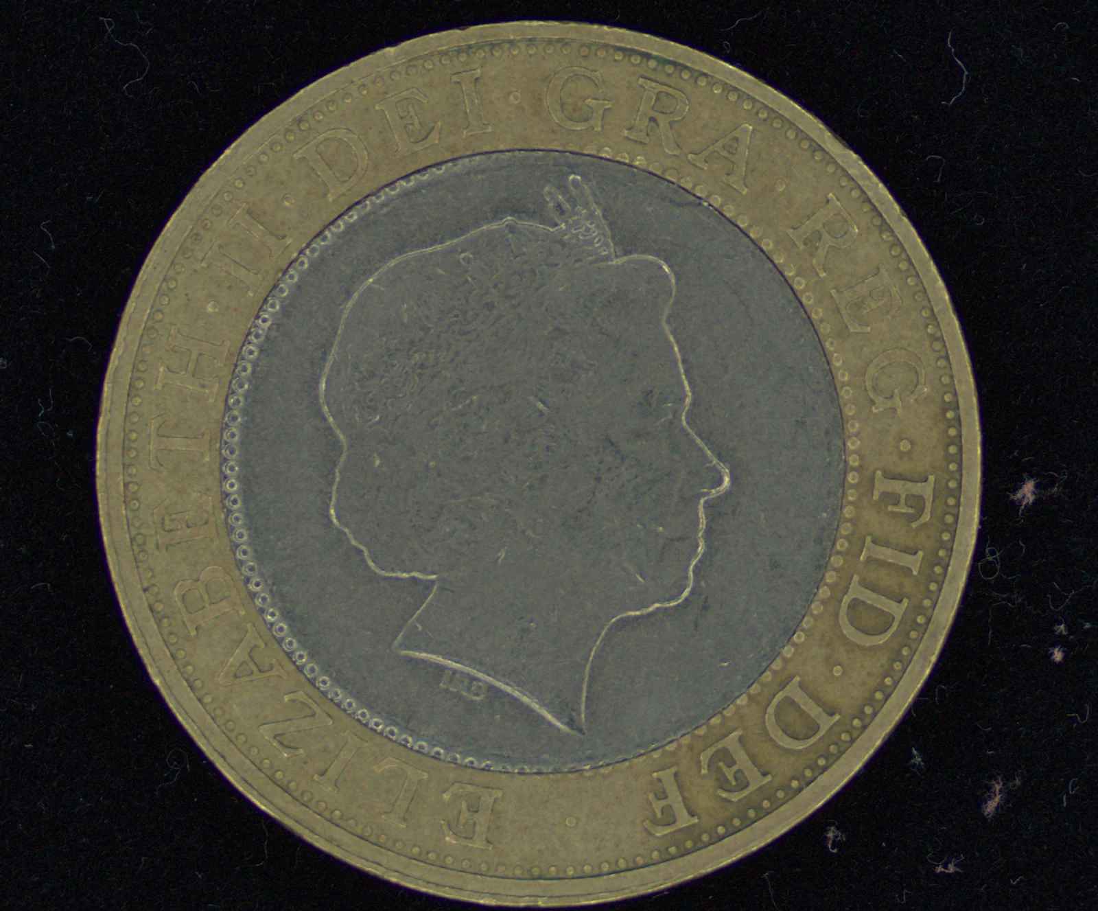
◀ Drag to compare ▶
This page uses this one coin and nothing else, so that what a single capture can yield is followed on the same subject from start to finish.
Experiment 01
The light can be decided afterwards.
What you see below is not a photograph. It is drawn by computing I = ρ (n · l) in your browser, on the spot, from the surface normal n and albedo (reflectance) ρ measured by FORESIGHT STEREO. Try moving the light position l.
Light position l = (0.00, 0.00, 1.00)
Centre = straight overhead. The further out, the lower the angle. You can drag on the pad, or directly on the image.
135°
38°
This is what “illumination-invariant” means.
Once a single capture has given you n and ρ, you can create any lighting you like afterwards. Put the other way round, the normal itself does not depend on how the light falls.
When the lighting on the floor changes, or daylight comes in from outside, the physical quantity of surface direction stays the same. This property is what we have put at the core of our work.
Computation, not generation.
What is running here is nothing more than arithmetic: I = ρ (n · l) applied to measured physical quantities. It is not producing a plausible-looking picture. Give the same input the same light and you get the same pixel values, however many times you try.
※ This relighting assumes Lambertian (diffuse) reflection only. It does not include the glare of specular reflection that appears on a real metal surface (→ Weaknesses).
The equation
One set of simultaneous
equations per pixel.
The direction of the light l is known. The captured brightness I is known too. What is unknown is that pixel's surface direction n and reflectance ρ.
Put g = ρn, and this becomes linear in g. There are three unknowns, so at least three images. With three it can be solved at every pixel: |g| is the albedo and g / |g| is the normal.
All that is being solved is a system of three equations in three unknowns, independently for each pixel. So the output resolution is exactly the camera's pixels. Unlike stereo, which searches for corresponding points, or structured light, which projects a pattern, the resolution is not set by the size of a search window or the coarseness of a pattern.
Camera and sample stay fixed; only the lights are switched, one at a time, to take N images. Because the imaging position does not move, the N images overlap pixel for pixel as they are.
Experiment 02
With fewer than three images,
there is no single answer.
Try changing the number of lights N. The normal is solved again from N images, and the deviation from the measured normal is shown as a mean angle. Whether there are enough equations for the three unknowns shows up directly in the picture.
The re-solved normal (surface direction encoded as colour; cropped to the centre of the coin)
4 images
Images used as input
These N images are simulated images, made with the same equation from the measured n and ρ (they are not photographs). Uniform random noise of ±5% is added to the brightness as observation noise.
Deviation from the measured normal —
The measured normal (for checking the answer)
N = 1, 2 — not enough equations.
With one or two equations for three unknowns, the normal is not uniquely determined. At N = 1 every pixel becomes a uniform surface facing the direction of the light, and the coin vanishes. At N = 2 the shape appears, but it is distorted, with one undetermined direction missing.
N ≧ 3 — solvable, and then more robust.
Three images solve it. Beyond that, the extra images work to average out noise through least squares. The error keeps creeping down after three not because resolution is rising but because the result is becoming more robust to noise. That is why real systems carry more lights than the minimum — that, and so that pixels falling into shadow can be discarded and the rest still solve. In our systems, TR-100 in the area-camera configuration has 8 directions, and TR-300 in the line-scan configuration has 4 (→ Line scan cameras).
Four outputs
This is what it means
for ρ and n to separate.
The result of solving the equation becomes the product's output as it is. From a single capture, four ways of seeing rise at the same time.
The image as the eye sees it.
The ordinary capture used as the reference. Reflection and shadow remain as they are.
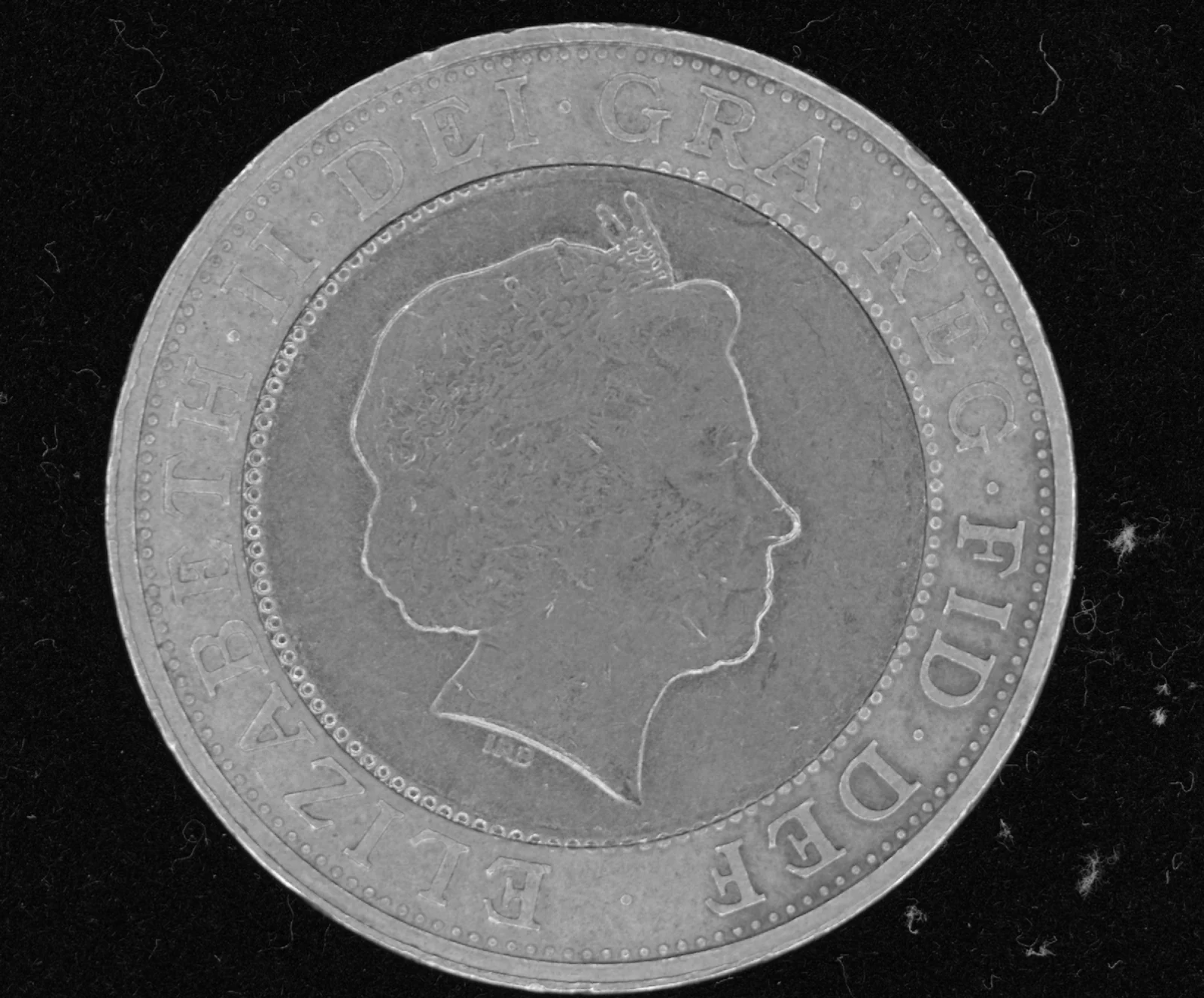
The ρ of the equation: the brightness of the material.
Albedo, with the shading discarded. This is the information that vanished when you “removed the albedo” in Experiment 01.
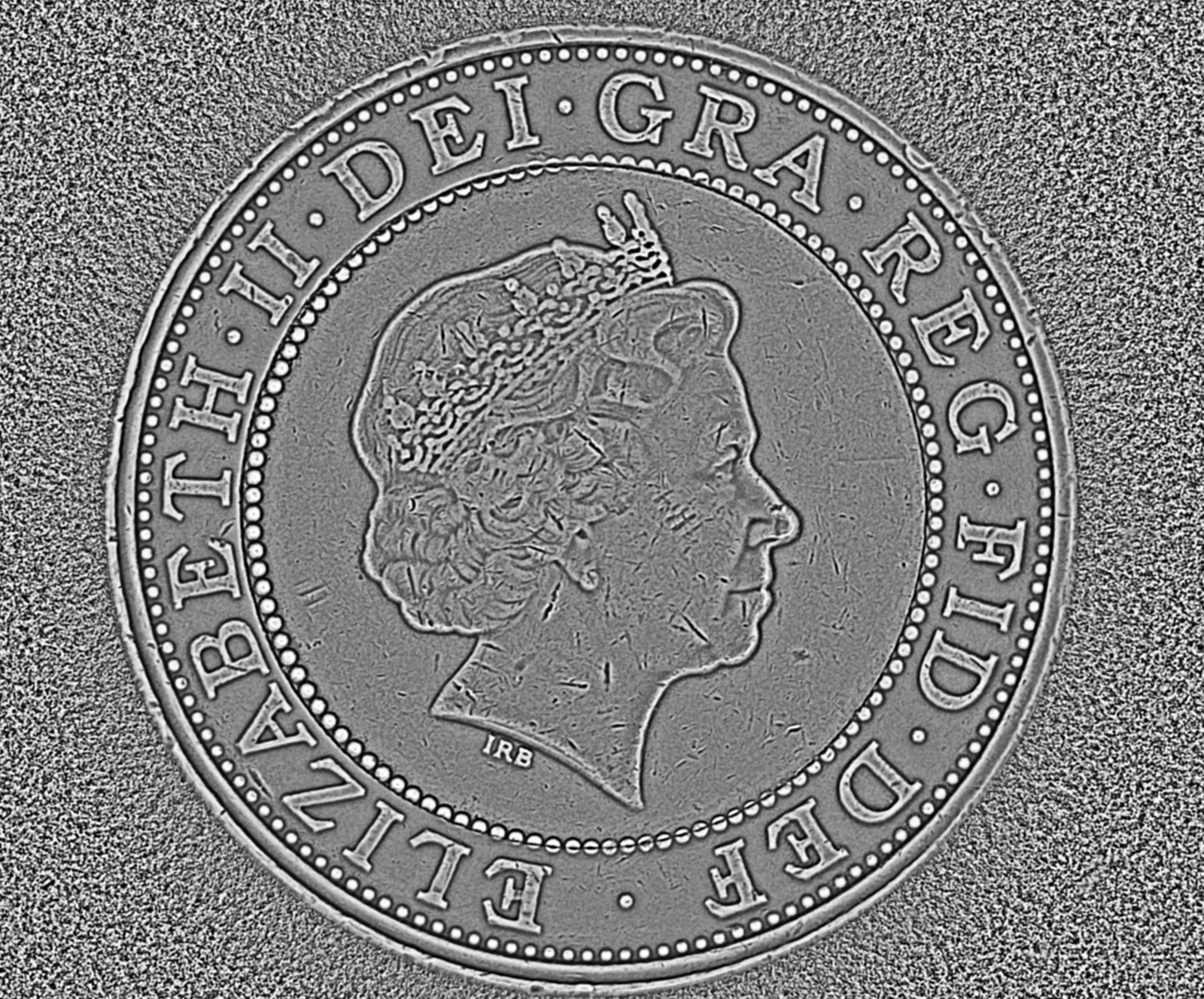
Height, rebuilt by joining up n.
Integrate surface direction across the whole face and it becomes relief. The scuffs and the engraved “IRB” stand up.
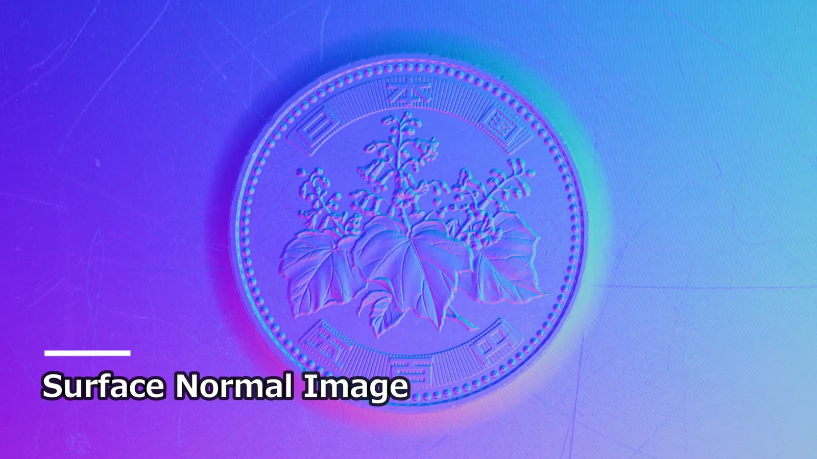
The n of the equation itself.
An illumination-invariant feature. It is this physical quantity that Experiments 01 and 02 were handling.
On the bench
Up to here, computation.
On a real system, it comes out like this.
Experiments 01 and 02 were calculations solved in your browser. Apply the same method on a real system to Japanese coins, and Live / Surface Normal / 3D Surface rise one after another. The relief of the engraving and the scuffs on the field both come out not as colour but as surface direction.
 2:16
TOMOMI RESEARCH / YouTube Watch on YouTube ↗
The footage is real output from our own system. The video is in Japanese. Nothing is loaded from YouTube until you press play (at that point the player switches to youtube-nocookie.com).
Strengths and limits
Both are called “3D”,
but they measure different things.
Photometric stereo is not an all-purpose 3D measurement. Its strengths and weaknesses are the exact reverse of those of triangulation-based methods.
| Photometric stereo | Triangulation (stereo, structured light) | |
|---|---|---|
| What it measures directly | Surface direction (normal) and reflectance | Position of points (distance) |
| What sets the resolution | The camera's pixels. Each pixel is solved independently | The search window for corresponding points; the fineness of the projected pattern |
| Strong at | Fine changes in height, such as shallow scratches, dents and steps | Large-scale shape, such as dimensions, warp and overall form |
| Weak at | Waviness over a wide surface; absolute height (error accumulates through integration) | Fine relief; finding corresponding points on glossy faces and transparent bodies |
| Conditions during capture | Camera and sample fixed. Only the lighting is switched, for N images | One to several images, depending on the method |
※ This is a general comparison between methods and does not represent the performance of any particular product. What can actually be seen depends on the object, its surface finish and the imaging conditions.
It has clear weaknesses, too.
This method rests on the assumption that “brightness is set by surface direction alone”. Real surfaces break that assumption in many places.
On metal and glossy faces, mirror reflection creates strong brightness that falls outside the assumption. Solved as it is, the normal at that pixel lies. It needs handling — adding lights and discarding those readings as outliers, for example.
For a pixel that falls into shadow under a given light, that light's equation cannot be used. Where light bounces back and forth inside a deep groove, the assumption breaks down too. The answer is to increase N and leave room to “solve with only the usable equations”.
Building height from normals means integrating, so error accumulates with distance. It is very strong on fine relief, but weak on low frequencies such as the warp of a whole sheet. That is work for triangulation-based methods.
The method assumes the N images overlap pixel for pixel, so it does not hold if the object moves while it is being captured. To use it on a moving line, this constraint has to be removed on the system side.
What we have developed in our own way is precisely this part: how to remove these constraints on the floor. For example, TR-300 is a continuous inspection system that turns images into 3D on a moving line.
Where it sits
Where this method sits.
Photometric stereo is a method, not a product name. In our products, the method is carried by Layer 01 of the three layers.
FORESIGHT STEREO®
A 3D imaging technique developed in our own way from photometric stereo. From illumination in many directions it takes the surface normal, independently of the lighting. Measurement that could not previously be reached, made to work on the floor.
E3 ENGINE®
The AI anomaly detection engine. It learns from good products only and puts a number on the distance from them, returning one of three verdicts: OK / Human_Check / NG. Read more →
TR series
The sensor and the decision brought together into a single unit that works on the floor. From a benchtop observation unit to continuous inspection on a line, to a robot-mounted cell.
※ The standalone software AI SMART MASK sits outside these three layers (it is pre-processing that decides “where to look”, and it makes no pass/fail decision).
Related
Products that run on this method
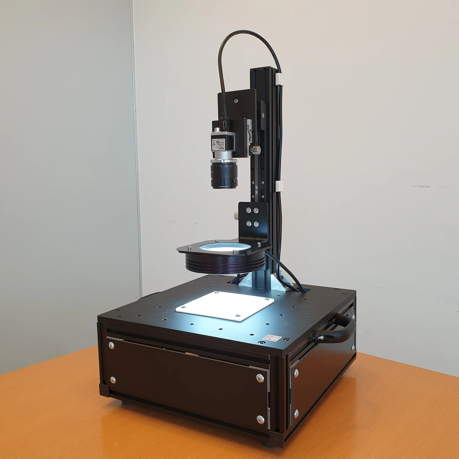
The unit for “seeing” first. Check the four outputs on this page with your own samples.
Read more →
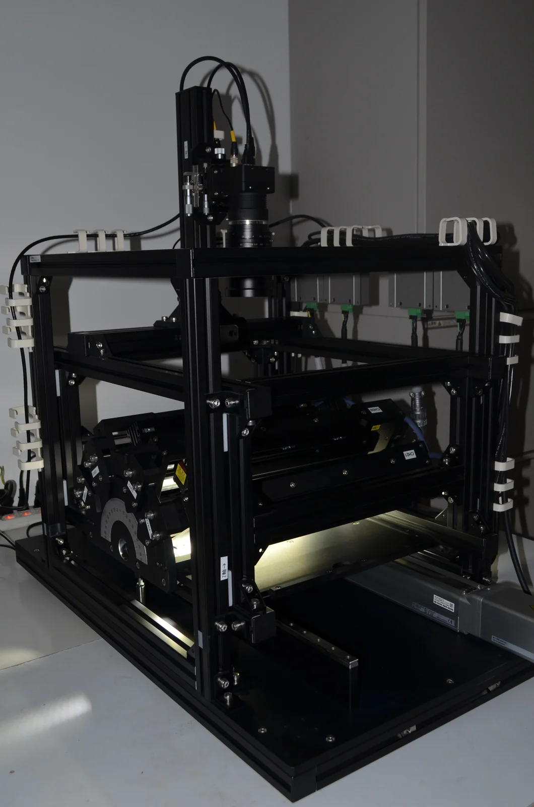
The model that removes the “things that move during capture” constraint. Turns images into 3D on a moving line.
Read more →
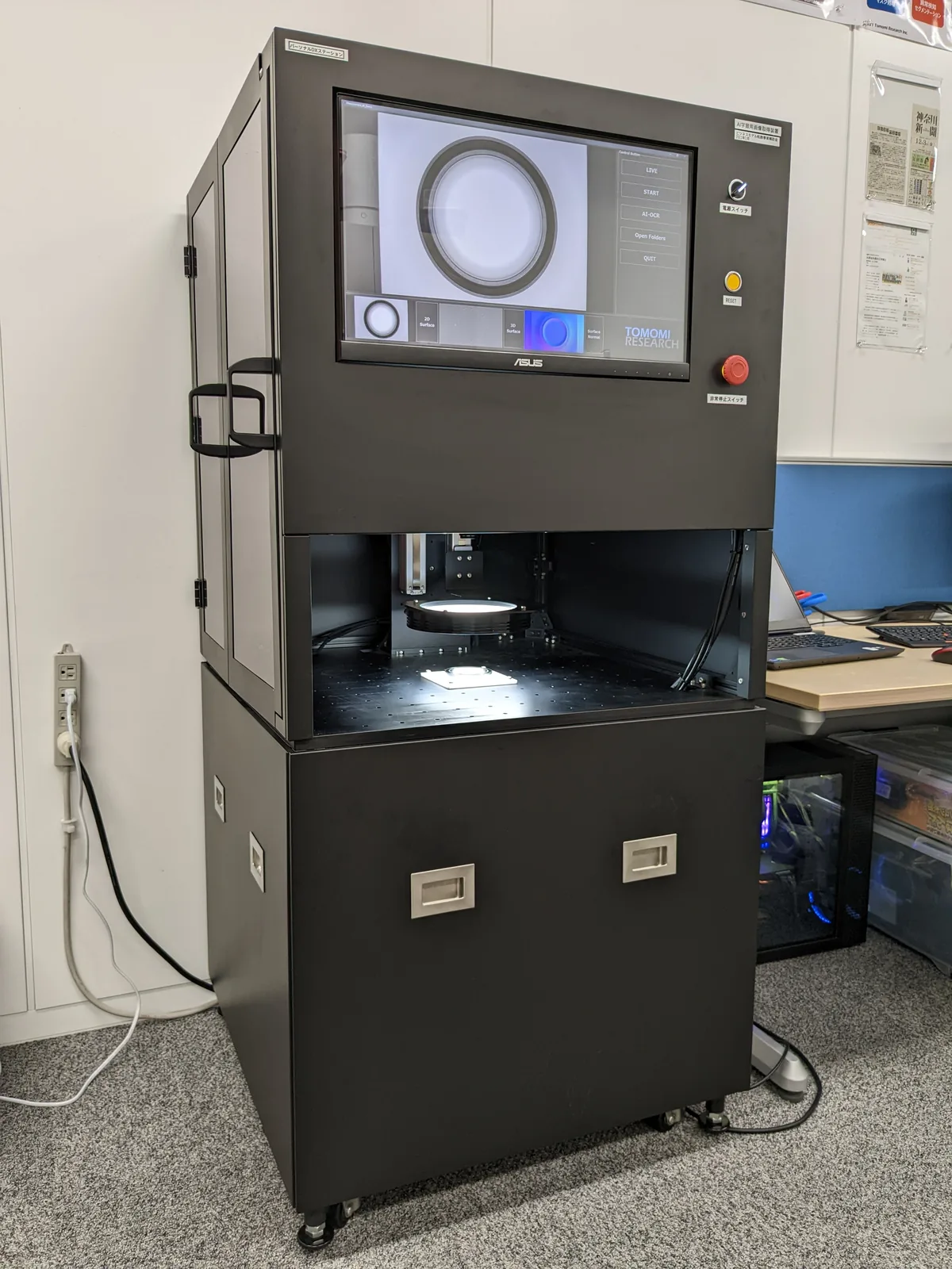
A configuration that puts everything from capture to verdict in one unit. It captures the normal and returns pass or fail on the spot.
Read more →
Contact
Can this method
see your object?
Whether it can be seen depends on the surface finish of the object and the height of the defect you want to see. This is as far as a screen can take you. Start by letting us take in your samples, capture them for real and return the four outputs to you.