Bump "Discoloration" or "Crushing"? Capturing a Semiconductor Chip Once with FORESIGHT STEREO to See Color and Shape Separately
 kotai2003
On semiconductor bump/pad arrays, many of the defects you need to find reside in "shape" (height, crushing, missing material). Yet "color" information such as oxidation and stains is mixed in on the surface, and because copper and solder reflect light strongly, bumps tend to get lost in illumination reflections (glare) in conventional 2D visual inspection. In this post, we captured one copper-colored semiconductor chip with our stereo 3D imaging technology FORESIGHT STEREO and present the results of taking four types of output from that single capture at the same time. Follow the four images in order to see how, once the color is peeled away, only the "shape" of the bumps rises up as a sea of protrusions.
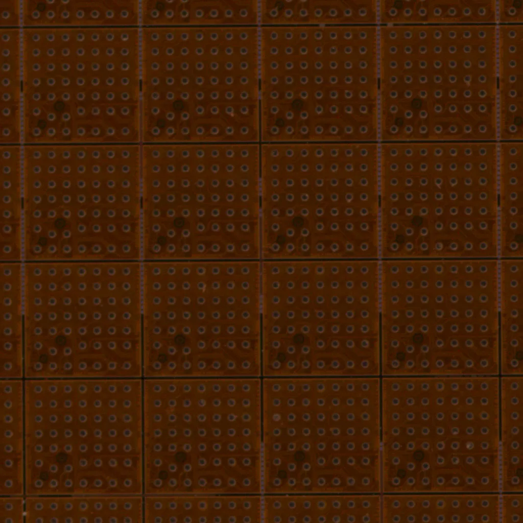
LIVE image of a semiconductor chip captured with FORESIGHT STEREO. Grid-like units are arranged on a copper-colored substrate, fine bumps are laid out in a regular array within each unit, and brown stain-like discoloration is visible in places
Why observe a semiconductor bump array?
The subject we chose is a copper-colored semiconductor chip/package substrate. Within each unit, divided into a grid by dicing streets (the lines that mark where chips are cut apart), fine bumps (pads) are arranged in a dense, regular array. From an inspection-technology standpoint, this sample concentrates several difficulties on a single surface.
- Color information: brown stain-like discoloration visible in some cells. Cues on the "color side," such as oxidation or dirt, lying flat on the surface
- Shape information: cues on the "shape side," where the surface itself has relief, such as the height and form of each bump, the fine relief of wiring traces, and steps at cell boundaries
On top of that, copper and solder are highly reflective materials. With an ordinary camera, reflection and shading mix, making it hard to tell shades of color from real relief. In other words, this chip is a sample that concentrates the hardest part of bump inspection: "color and shape are mixed, and the reflection is strong."
What is FORESIGHT STEREO? Four outputs in one shot
FORESIGHT STEREO is TOMOMI RESEARCH's stereo 3D imaging technology. Its key feature is that it generates four types of output simultaneously from a single capture.
- LIVE image: the appearance just as the human eye sees it
- 2D Texture: a layer that extracts only the surface's "color and pattern"
- 3D Surface: a layer that reconstructs only the surface's "shape (relief)"
- Surface Normal: intermediate data that encodes the surface's "orientation"
Rather than recapturing or adding separate processes, a single shot lets you lay out the "color layer" and the "shape layer" side by side. This simultaneity translates directly into throughput on the inspection floor. Now let us look at the four outputs in order.
(1) LIVE image: the "starting point," with color and shape mixed
First is the LIVE image, the state as seen by the human eye (the image at the top).
On the gleaming copper-colored substrate, grid-like units are neatly arranged. Inside each unit is a "sea of bumps," countless tiny bumps laid out in a regular pattern. Yet here and there across the image, brown stain-like discoloration can also be seen. Here, "color" and "shape" are melted together in a single picture. Is that stain dirt or discoloration on the surface, or a shadow cast by a crushed bump? The human eye cannot tell. This "mixed state" is the starting point that we will now separate.
(2) 2D Texture: keeping only color (albedo)
Next is the 2D Texture, a layer that extracts only color.
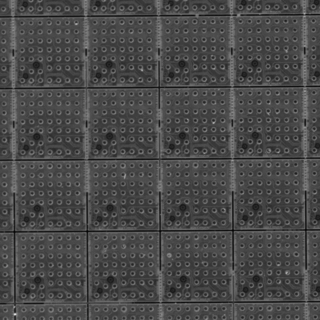
2D Texture output of FORESIGHT STEREO. A grayscale image with shading removed, extracting only color and pattern (albedo). The arrangement of bumps and the stain-like shading can be read flatly
Shading and highlights from the illumination have been removed, and the arrangement of bumps and the unevenness of discoloration can now be read at a flat, uniform brightness. What is being extracted here is technically called albedo (the color and reflectance inherent to the material itself), in other words "the base color and pattern of the material, undisturbed by illumination or the shadows of relief."
- What it keeps: surface color information such as discoloration, stains, and dirt
- What it discards: shadows and highlights created by relief
Because color unevenness alone can be evaluated without being misled by the shadows of relief, it is well suited to examining "color-side" defects such as oxidation, discoloration, dirt, and adhered foreign matter. The stain-like shading that caught our eye in the LIVE image also remains here as a pure "color pattern."
(3) 3D Surface: discarding color, keeping only the shape of the bumps (the highlight of this article)
And now the star of this post, the 3D Surface.
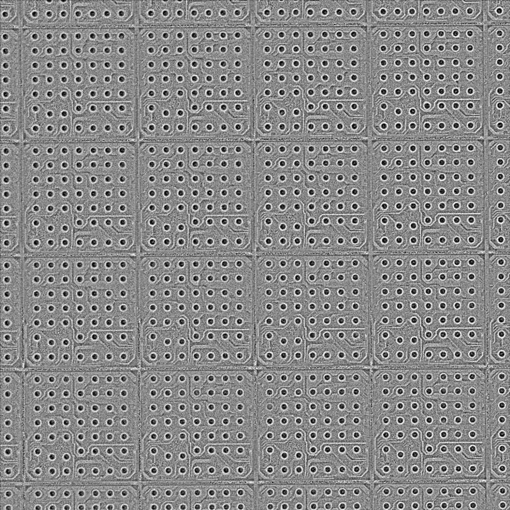
3D Surface reconstructed with FORESIGHT STEREO. Color and stains disappear, each bump rises as part of a regular sea of protrusions, and even L-shaped wiring traces and steps at cell boundaries emerge as relief
All the color has vanished, and only the relief emerges, like a relief carving. The brown stains that stood out until now have almost disappeared here. This is a decisive clue: if a stain disappears, it tells you that it is "not shape, meaning surface discoloration or dirt."
- Sea of bumps: the bumps in each unit rise all at once as regular protrusions. Differences in the height and roundness of each one, and clues to chipping or crushing, can be read.
- Wiring traces: L-shaped wiring lines inside the cells, inconspicuous in the LIVE image, become apparent as fine relief.
- Steps at cell boundaries: steps between sections along the dicing streets rise as smooth undulations.
What is happening here is that "color that merely sits on a flat surface disappears, because it does not exist as shape." The color of the stains does not appear in the 3D Surface; only the areas where the surface is physically deformed remain. In other words, FORESIGHT STEREO removes "what color sits on top" and extracts purely "what shape it has." This is a viewpoint for examining shape-side cues such as missing, crushed, or height-varying bumps. It can also serve as a foothold for reading whether bump heights are even (coplanarity, the evenness of bump heights).
(4) Surface Normal: expressing the "orientation" of the surface as color
Finally, the Surface Normal, the intermediate data from which the 3D Surface was reconstructed.

Surface Normal output of FORESIGHT STEREO. A normal map encoding the surface orientation of each pixel as color. The surface is blue overall, facing upward, with changes in orientation scattered at each bump position
It is a distinctive map that looks as if the whole image is glowing in blue tones. This is the surface normal (the direction in which the surface at each pixel faces) encoded as color. A "normal" is like an arrow showing which way the surface at that point faces, and the color changes where the slope of the surface changes, that is, at edges and where bumps rise.
In this image, the flat substrate surface appears as uniform blue (facing straight up), and within it points where the orientation changes at each bump position are scattered in a regular pattern. Because it is highly sensitive to minute relief and rising edges, it not only serves as the foundation for 3D Surface reconstruction but also functions as raw data for reading clues to the rise of each individual bump, and slight steps or chips.
What it means on the inspection floor: separating "color or shape"
Looking at the four outputs side by side, the value FORESIGHT STEREO brings to bump inspection on the floor becomes clear.
- Separating discoloration from missing material: by looking at the 2D Texture (color) and the 3D Surface (shape) separately, you can tell in one shot whether something is "discoloration or dirt (a texture defect)" or "a missing or crushed bump (a shape defect)."
- Strong on highly reflective materials: even with materials like copper and solder, which reflect strongly and whose bumps get lost in illumination reflections with an ordinary camera, the bumps can be captured as shape (relief).
- Observing bump shape and height variation: because the bumps rise as a sea of protrusions, you gain clues to chipping, crushing, and uneven heights, and a foothold for reading coplanarity (the evenness of bump heights).
- Complete in one shot: the four viewpoints are obtained at the same time in a single capture instead of being recaptured separately, so inspection throughput is not reduced.
Note that this is only an observation demo on a single sample and does not guarantee performance for every material and every defect. Even so, the four images speak eloquently to how the idea of "looking at color and shape separately" could change the inspection of bump arrays, where color and shape are mixed and reflection is strong.
Summary
- FORESIGHT STEREO is a stereo 3D imaging technology that generates four outputs simultaneously from a single capture: LIVE image, 2D Texture (color), 3D Surface (shape), and Surface Normal (orientation).
- On the semiconductor bump array, color information such as discoloration remained in the 2D Texture, while in the 3D Surface the color (stains) disappeared and only the protrusions of each bump emerged. "Color" and "shape," which mix for the human eye, can be separated into different layers.
- Being able to separate color and shape connects directly to on-site challenges such as separating discoloration from missing material, inspecting highly reflective materials, and observing bump height variation (coplanarity).